VAT 650 Series Installation, Operating, & Maintenance Instructions
Dn 100-250 i.d. 4“ - 10”, pendulum control & isolation valve with cc-link interface
Hide thumbs
Also See for 650 Series:
Table of Contents
Advertisement
Quick Links
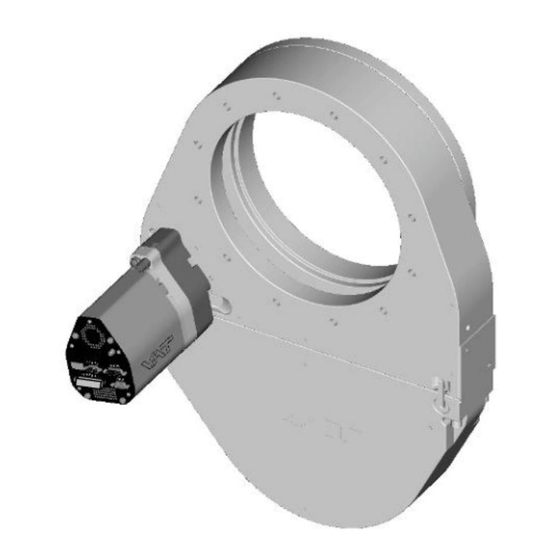
Pendulum control & isolation valve
with CC-Link interface
This manual is valid for the valve ordering number(s):
650 . . - . . GL - . . . .
(1 sensor input)
650 . . - . . GN - . . . .
(2 sensor inputs)
650 . . - . . AL - . . . .
(1 sensor input / 15V SPS)
650 . . - . . AN - . . . .
(2 sensor inputs / 15V SPS)
650 . . - . . HL - . . . .
(1 sensor input / PFO)
650 . . - . . HN - . . . .
(2 sensor inputs / PFO)
650 . . - . . CL - . . . .
(1 sensor input / 15V SPS / PFO)
650 . . - . . CN - . . . .
(2 sensor inputs / 15V SPS / PFO)
SPS = Sensor Power Supply
configured with firmware
650C.1E.15
The fabrication number is indicated on each product as per the label
below (or similar):
made in Switzerland
Fabrication No.:
patented
650 . . – . . . . – . . . . / . . . .
A – . . . . . .
Explanation of symbols:
Read declaration carefully before you start any other
action!
Attention!
Product is in conformity with EC guidelines,
if applicable!
Disconnect electrical power and compressed air
lines. Do not touch parts under voltage!
Read these «Installation, Operating & Maintenance Instructions» and the enclosed «General
Safety Instructions» carefully before you start any other action!
VAT Vakuumventile AG, CH-9469 Haag, Switzerland
Tel +41 81 771 61 61 Fax +41 81 771 48 30 CH@vatvalve.com www.vatvalve.com
Installation, Operating & Maintenance Instructions
Series 650 DN 100-250 (I.D. 4" - 10"), CC-Link
PFO = Power Failure Option
. .
Fabrication number
sample picture
Keep body parts and objects away from the valve
opening!
Hot surfaces; do not touch!
Loaded springs and/or air cushions are potential
hazards!
Wear gloves!
280271EF
2012-10-02
1/84
Advertisement
Table of Contents

Related Manuals for VAT 650 Series


Summary of Contents for VAT 650 Series
- Page 1 Do not touch parts under voltage! Read these «Installation, Operating & Maintenance Instructions» and the enclosed «General Safety Instructions» carefully before you start any other action! VAT Vakuumventile AG, CH-9469 Haag, Switzerland 280271EF 1/84 Tel +41 81 771 61 61 Fax +41 81 771 48 30 CH@vatvalve.com www.vatvalve.com...
- Page 2 VAT products. The VAT firmware contains a limited, time unlimited user license. The VAT firmware may not be used for purposes other than those intended nor is it permitted to make copies of the VAT firmware. In particular, it is strictly forbidden to give copies of the VAT firmware to other people.
-
Page 3: Table Of Contents
4 Trouble shooting ..............................63 Additional CC-Link warning ..........................65 5 Maintenance & repairs ............................66 Maintenance procedures ..........................67 VAT Vakuumventile AG, CH-9469 Haag, Switzerland 280271EF 3/84 Tel +41 81 771 61 61 Fax +41 81 771 48 30 CH@vatvalve.com www.vatvalve.com... - Page 4 Valve unit ............................... 81 Accessories ..............................82 7.3.1 Centering ring with Viton o-ring ......................83 8 Warranty ................................. 84 VAT Vakuumventile AG, CH-9469 Haag, Switzerland 280271EF 4/84 Tel +41 81 771 61 61 Fax +41 81 771 48 30 CH@vatvalve.com www.vatvalve.com 2012-10-02...
-
Page 5: Use Of Product
This product is a throttling pendulum valve with isolation functionality. It is intended to use for downstream pressure control applications. Use product for clean and dry indoor vacuum applications under the conditions indicated in chapter «Technical data» only! Other applications are only allowed with the written permission of VAT. Technical data Control and actuating unit (α) - Page 6 Refer to chapter «Sensor supply concepts» for details. Refer to chapter «Schematics» for details. PFO = Power Failure Option. Refer to «Behavior in case of power failure» for details. VAT Vakuumventile AG, CH-9469 Haag, Switzerland 280271EF 6/84 Tel +41 81 771 61 61 Fax +41 81 771 48 30 CH@vatvalve.com www.vatvalve.com...
- Page 7 15 l/s molecular flow) Dimensions Refer to dimensional drawing of specific valve ordering number (available on request) VAT Vakuumventile AG, CH-9469 Haag, Switzerland 280271EF 7/84 Tel +41 81 771 61 61 Fax +41 81 771 48 30 CH@vatvalve.com www.vatvalve.com 2012-10-02...
-
Page 8: Installation
4 - 7 bar / 55 - 100 psi (above ATM) Use only clean, dry or slightly oiled air. Connection overview: Connectors at controller panel: VAT Vakuumventile AG, CH-9469 Haag, Switzerland 280271EF 8/84 Tel +41 81 771 61 61 Fax +41 81 771 48 30 CH@vatvalve.com www.vatvalve.com... - Page 9 This valve has a double sealed rotary feedthrough and optionally an intermediate pumping port for the actuator shaft. This port (1/8“ ISO/NPT) could be connected to the vacuum line, see Figure 2 below. This valve may optionally be equipped with a heating device. Connect VAT heating device according to manual of respective heating device.
-
Page 10: Tightening Torque
0.63 (65048 - ..- ..) Refer to «Spare parts and accessories» for centering rings ordering numbers. VAT Vakuumventile AG, CH-9469 Haag, Switzerland 280271EF 10/84 Tel +41 81 771 61 61 Fax +41 81 771 48 30 CH@vatvalve.com www.vatvalve.com... -
Page 11: Mounting With O-Ring In Grooves
For a combination of both forces (F and M) the values are invalid. Verify that the depth of the mounting screws is min. 1 x thread diameter. Please contact VAT for more information. VAT Vakuumventile AG, CH-9469 Haag, Switzerland 280271EF 11/84 Tel +41 81 771 61 61 Fax +41 81 771 48 30 CH@vatvalve.com www.vatvalve.com... -
Page 12: Requirements To Sensor Connection
Dynamic stray magnetic fields may introduce noise to sensor output and should be avoided or shielded. VAT Vakuumventile AG, CH-9469 Haag, Switzerland 280271EF 12/84 Tel +41 81 771 61 61 Fax +41 81 771 48 30 CH@vatvalve.com www.vatvalve.com... -
Page 13: Electrical Connection
It is also possible to connect the ground strap at system chamber if it is well connected to PE. Note: Avoid low chassis cross section to the system PE connection. (Min. same cross section as ground strap) VAT Vakuumventile AG, CH-9469 Haag, Switzerland 280271EF 13/84 Tel +41 81 771 61 61 Fax +41 81 771 48 30 CH@vatvalve.com www.vatvalve.com... -
Page 14: Sensor Supply Concepts
650 . . - . . A . - ../ 650 . . - . . C . - ..SPS module included Note: The SPS module can be retrofitted. Refer to chapter «Retrofit / replacement procedure» for instruction. VAT Vakuumventile AG, CH-9469 Haag, Switzerland 280271EF 14/84 Tel +41 81 771 61 61 Fax +41 81 771 48 30 CH@vatvalve.com www.vatvalve.com... -
Page 15: Power And Sensor Connection (+24 Vdc Sensors)
Connect the +24 VDC sensors at DB–15 female sensor connector exactly as shown in the drawing above. Do not connect other pins, that may damage power supply or controller! Connector: Use only screws with 4-40UNC thread for fastening the connectors! VAT Vakuumventile AG, CH-9469 Haag, Switzerland 280271EF 15/84 Tel +41 81 771 61 61 Fax +41 81 771 48 30 CH@vatvalve.com www.vatvalve.com... - Page 16 Connect the +24 VDC sensors at DB–15 female sensor connector exactly as shown in the drawing above. Do not connect other pins, that may damage power supply or controller! Connector: Use only screws with 4-40UNC thread for fastening the connectors! VAT Vakuumventile AG, CH-9469 Haag, Switzerland 280271EF 16/84 Tel +41 81 771 61 61 Fax +41 81 771 48 30 CH@vatvalve.com www.vatvalve.com...
-
Page 17: Power And Sensor Connection ( 15 Vdc Sensors) Without Optional Sps Module
Connect the 15 VDC sensors at DB–15 female sensor connector exactly as shown in the drawing above. Do not connect other pins, that may damage power supply or controller! Connector: Use only screws with 4-40UNC thread for fastening the connectors! VAT Vakuumventile AG, CH-9469 Haag, Switzerland 280271EF 17/84 Tel +41 81 771 61 61 Fax +41 81 771 48 30 CH@vatvalve.com www.vatvalve.com... - Page 18 Connect the 15 VDC sensors at DB–15 female sensor connector exactly as shown in the drawing above. Do not connect other pins, that may damage power supply or controller! Connector: Use only screws with 4-40UNC thread for fastening the connectors! VAT Vakuumventile AG, CH-9469 Haag, Switzerland 280271EF 18/84 Tel +41 81 771 61 61 Fax +41 81 771 48 30 CH@vatvalve.com www.vatvalve.com...
-
Page 19: Power And Sensor Connection ( 15 Vdc Sensors) With Optional Sps Module
Connect the 15 VDC sensors at DB–15 female sensor connector exactly as shown in the drawing above. Do not connect other pins, that may damage power supply or controller! Connector: Use only screws with 4-40UNC thread for fastening the connectors! VAT Vakuumventile AG, CH-9469 Haag, Switzerland 280271EF 19/84 Tel +41 81 771 61 61 Fax +41 81 771 48 30 CH@vatvalve.com www.vatvalve.com... -
Page 20: Cc-Link Interface Connection
Note: The valve can be defined as «first station», «…stations…» between first and last, or «last station». If the valve at first or last station, «TR» must be installed between 1 (DA) and 2 (DB). Note: The station type for VAT valves are: Version 2 Remote Device Station. VAT Vakuumventile AG, CH-9469 Haag, Switzerland... - Page 21 COMBICON Strain-relief screw for shield mesh and cable CC-Link wires Connector housing VAT Shield mesh CC-Link cable VAT Vakuumventile AG, CH-9469 Haag, Switzerland 280271EF 21/84 Tel +41 81 771 61 61 Fax +41 81 771 48 30 CH@vatvalve.com www.vatvalve.com 2012-10-02...
- Page 22 Cut off the shield wires about 15mm Side-cutting pliers Separate the shield wires in two equal quantum and place them 180° opposite VAT Vakuumventile AG, CH-9469 Haag, Switzerland 280271EF 22/84 Tel +41 81 771 61 61 Fax +41 81 771 48 30 CH@vatvalve.com www.vatvalve.com...
- Page 23 11. Fasten the strain-relief screw until the cable Screw driver can not pulled out by manual force size 4 VAT Vakuumventile AG, CH-9469 Haag, Switzerland 280271EF 23/84 Tel +41 81 771 61 61 Fax +41 81 771 48 30 CH@vatvalve.com www.vatvalve.com...
- Page 24 15. Push the cover down to controller and Pozidriv screw driver fasten the cover screws (sample picture) size 2 VAT Vakuumventile AG, CH-9469 Haag, Switzerland 280271EF 24/84 Tel +41 81 771 61 61 Fax +41 81 771 48 30 CH@vatvalve.com www.vatvalve.com...
- Page 25 Installation, Operating & Maintenance Instructions Series 650 DN 100-250 (I.D. 4“ - 10”), CC-Link Connector type: COMBICON 2.5 / 5 - ST – 5, 08 with special VAT housing PIN interface Signal Color of isolator (CC-Link wires) Comment connector Blue...
-
Page 26: Logic I/O
Local commands Configuration with switch for digital input: Note: Do not connect other pins than indicated in the schematics above! Connector type: Binder M8 (99-3363-00-04). VAT Vakuumventile AG, CH-9469 Haag, Switzerland 280271EF 26/84 Tel +41 81 771 61 61 Fax +41 81 771 48 30 CH@vatvalve.com www.vatvalve.com... -
Page 27: Digital Input
The service port (connector: SERVICE) allows to connect the valve to a RS232 port of a computer. This requires a service cable and software from VAT. You can either use our freeware 'Control View', which can be downloaded from www.vatvalve.com or purchase our 'Control Performance Analyzer'. -
Page 28: Operation
Local operation means that the valve is operated via the service port using a computer or the Service Box 2. When using a computer, a service cable and a software from VAT are required. You can either download our freeware 'Control View' from or purchase our 'Control Performance Analyzer'. -
Page 29: Remote Operation
Valve position after power up is closed Valve position after power up is open Refer also to chapter «Display information». VAT Vakuumventile AG, CH-9469 Haag, Switzerland 280271EF 29/84 Tel +41 81 771 61 61 Fax +41 81 771 48 30 CH@vatvalve.com www.vatvalve.com... -
Page 30: Behavior In Case Of Power Failure
*) Provided that battery pack of the VAT controller is charged. Charging time after power up is 2 minutes max.. All parameters are stored in a power fail save memory. VAT Vakuumventile AG, CH-9469 Haag, Switzerland... -
Page 31: Display Information
1) SPS = optional ±15 VDC Sensor Power Supply module 2) PFO = optional Power Failure Option VAT Vakuumventile AG, CH-9469 Haag, Switzerland 280271EF 31/84 Tel +41 81 771 61 61 Fax +41 81 771 48 30 CH@vatvalve.com www.vatvalve.com... - Page 32 (< 4 bar / 55 psi) Compressed air on exhaust Fatal error occurred Error code. Refer to «Trouble shooting» for details VAT Vakuumventile AG, CH-9469 Haag, Switzerland 280271EF 32/84 Tel +41 81 771 61 61 Fax +41 81 771 48 30 CH@vatvalve.com www.vatvalve.com...
-
Page 33: Cc-Link Leds
Red, flickering CRC error (temporary flickering) Red, flashing Station Number or Baud rate has changed since startup (flashing) VAT Vakuumventile AG, CH-9469 Haag, Switzerland 280271EF 33/84 Tel +41 81 771 61 61 Fax +41 81 771 48 30 CH@vatvalve.com www.vatvalve.com... -
Page 34: Setup Procedure
Refer to chapter «LEARN» for details. LEARN Note: Without LEARN the valve is not able to run pressure control VAT Vakuumventile AG, CH-9469 Haag, Switzerland 280271EF 34/84 Tel +41 81 771 61 61 Fax +41 81 771 48 30 CH@vatvalve.com www.vatvalve.com... -
Page 35: Cc-Link Configuration
Series 650 DN 100-250 (I.D. 4“ - 10”), CC-Link 3.6.1 CC-Link configuration Note: The station type for VAT valves are: Version 2 Remote Device Station. Station Number The «station number» is used to distinguish between stations on the CC-Link network. Unique station numbers in consecutive order without duplication must be used, when assigning stations to the CC-Link network. - Page 36 Extended cyclic settings: In the extended cyclic transmission (only Ver.2), the extended cyclic points can be set as 2 times, 4 times or 8 times of the normal cyclic transmission points. The VAT slave supports two combinations of the CC-Link parameter settings. Value Operational settings CC-Link Ver.2 / Occupies 1 station / Octuple expanded cyclic...
- Page 37 Note: If at start up the data type value in the memory is out of range the default value is taken. In this case the data type is set to default value (0 = singed integer) and the get command i:23 add a string “False”: VAT Vakuumventile AG, CH-9469 Haag, Switzerland 280271EF 37/84 Tel +41 81 771 61 61 Fax +41 81 771 48 30 CH@vatvalve.com www.vatvalve.com...
- Page 38 The format of y and z has following syntax: _ _ _ _ _ _ _ _._ _ _ _ _ Examples: i:2400-0012345.12345to00123456.12345 i:2401-0001000.00000to00001000.00000 i:240200001000.00000to00001500.00000 Example «get-command» with Terminal: Get the range of Pressure Sensor 1: VAT Vakuumventile AG, CH-9469 Haag, Switzerland 280271EF 38/84 Tel +41 81 771 61 61 Fax +41 81 771 48 30 CH@vatvalve.com www.vatvalve.com 2012-10-02...
-
Page 39: Logic I/O Configuration
Note: The internal accuracy of valve is for all positions 100‟000 steps and for all pressures 1‟000‟000 steps. If the range of pressure and position values is rising, the accuracy of pressure and position will not rise. There is only the gain factor between the VAT valve and the CC-Link Master which will be adapted. Note:... -
Page 40: Valve And Sensor Configuration
Do 2 sensor configuration in menu „Setup / Sensor‟. Note: Read first current configuration and do not change reserved bits when sending new configuration. VAT Vakuumventile AG, CH-9469 Haag, Switzerland 280271EF 40/84 Tel +41 81 771 61 61 Fax +41 81 771 48 30 CH@vatvalve.com www.vatvalve.com... -
Page 41: Zero
Note: Do not perform ZERO, if the base pressure of your vacuum system is higher than 1‰ of sensor full scale. We recommend disabling ZERO function in this case; refer to «Valve and sensor configuration» of the setup procedure. Otherwise incorrect pressure reading is the result. VAT Vakuumventile AG, CH-9469 Haag, Switzerland 280271EF 41/84 Tel +41 81 771 61 61 Fax +41 81 771 48 30 CH@vatvalve.com www.vatvalve.com... -
Page 42: Learn
Note: Learn may take several minutes. Do not interrupt the routine as a single full run is required to ensure fast and accurate pressure control. The PID controller covers 5% to 5000% of the gas flow which was used for learn. If learn finished the valve goes to position mode. VAT Vakuumventile AG, CH-9469 Haag, Switzerland 280271EF 42/84 Tel +41 81 771 61 61 Fax +41 81 771 48 30 CH@vatvalve.com www.vatvalve.com... -
Page 43: Close Valve
MODE SETPOINT» for details) In «OUTUT Buffer» > «CONTROL MODE SETPOINT» Push OPEN button Select [Open] (value = 4) VAT Vakuumventile AG, CH-9469 Haag, Switzerland 280271EF 43/84 Tel +41 81 771 61 61 Fax +41 81 771 48 30 CH@vatvalve.com www.vatvalve.com 2012-10-02... -
Page 44: Position Control
Select or enter pressure setpoint In «OUTPUT Buffer» > «CONTROL MODE SETPOINT» Select [Pressure] (value = 5) VAT Vakuumventile AG, CH-9469 Haag, Switzerland 280271EF 44/84 Tel +41 81 771 61 61 Fax +41 81 771 48 30 CH@vatvalve.com www.vatvalve.com 2012-10-02... -
Page 45: Pressure Control Operation With 2 Sensors
PRESSURE output in this range is a blend between both sensors. Note: Make sure that both sensors are calibrated. Note: Do not close optional gauge isolation valves during the transition phase between the sensors. VAT Vakuumventile AG, CH-9469 Haag, Switzerland 280271EF 45/84 Tel +41 81 771 61 61 Fax +41 81 771 48 30 CH@vatvalve.com www.vatvalve.com... -
Page 46: Tuning Of Control Performance
Pumping speed (l/s) and pump type (e.g. turbo pump) System description Problem description Send diagnostic file with and all required information to tuning-support@vat.ch VAT Vakuumventile AG, CH-9469 Haag, Switzerland 280271EF 46/84 Tel +41 81 771 61 61 Fax +41 81 771 48 30 CH@vatvalve.com www.vatvalve.com 2012-10-02... - Page 47 Go to „Setup / Control Parameter‟ menu. Note: It‟s not possible to do „Sensor delay adjustment„ via CC-Link. Select sensor delay. VAT Vakuumventile AG, CH-9469 Haag, Switzerland 280271EF 47/84 Tel +41 81 771 61 61 Fax +41 81 771 48 30 CH@vatvalve.com www.vatvalve.com...
- Page 48 Go to „Setup / Control Parameter‟ menu. Note: It‟s not possible to do „Setpoint ramp adjustment„ via CC-Link. Select setpoint ramp. VAT Vakuumventile AG, CH-9469 Haag, Switzerland 280271EF 48/84 Tel +41 81 771 61 61 Fax +41 81 771 48 30 CH@vatvalve.com www.vatvalve.com...
- Page 49 Go to „Setup / Control Parameter‟ menu. Select valve Note: It‟s not possible to do „Valve speed adjustment„ speed. via CC-Link. VAT Vakuumventile AG, CH-9469 Haag, Switzerland 280271EF 49/84 Tel +41 81 771 61 61 Fax +41 81 771 48 30 CH@vatvalve.com www.vatvalve.com...
-
Page 50: Cc-Link Interface Connection Setup
3.11 CC-Link interface connection setup 3.11.1 CC-Link Handshaking Before the CC-Link slave station (VAT valve) can be operated by the CC-Link Master (PLC), handshaking is necessary. If the handshake is not done, no data from the master will be transmitted to station. -
Page 51: Location Of The Handshaking Bits
: Address assigned to the master module by the station number setting. This means that the address range for this slave begins at address m of the master. n : Dependent on the VAT Operational settings mode (number of occupied stations and number of extension cycles) ... -
Page 52: Example Of The Handshaking By A Plc-Program
3.11.3 Example of the handshaking by a PLC-program The following program sends an answer to the VAT CC-Link station which return a “Remote READY” flag. It is important to correct register address is used. In this example the address for this slave station (valve) starts at 1000 (hex). So m = 100 (see capture Location of the handshaking bits). -
Page 53: Cc-Link Interface (Process Data - Cyclic Communication)
Not used – reserved Not used – reserved Note: For data consistency make sure your master PLC is supporting “block guarantee of cyclic data per station”. VAT Vakuumventile AG, CH-9469 Haag, Switzerland 280271EF 53/84 Tel +41 81 771 61 61 Fax +41 81 771 48 30 CH@vatvalve.com www.vatvalve.com... - Page 54 NOT USED (reserved) NOT USED (reserved) To adjust range refer to chapter: «Range of pressure and position values» VAT Vakuumventile AG, CH-9469 Haag, Switzerland 280271EF 54/84 Tel +41 81 771 61 61 Fax +41 81 771 48 30 CH@vatvalve.com www.vatvalve.com...
- Page 55 1st step : set bit (01) 4. from locked to remote 1st step : reset bit (10) 5-15 NOT USED (reserved) VAT Vakuumventile AG, CH-9469 Haag, Switzerland 280271EF 55/84 Tel +41 81 771 61 61 Fax +41 81 771 48 30 CH@vatvalve.com www.vatvalve.com 2012-10-02...
-
Page 56: Input Buffer (Master Plc)
Not used – reserved Not used – reserved Not used – reserved Not used – reserved Not used – reserved VAT Vakuumventile AG, CH-9469 Haag, Switzerland 280271EF 56/84 Tel +41 81 771 61 61 Fax +41 81 771 48 30 CH@vatvalve.com www.vatvalve.com 2012-10-02... - Page 57 22 = valve blocked 25 = step loss during synch mode 40 = motor driver fault VAT Vakuumventile AG, CH-9469 Haag, Switzerland 280271EF 57/84 Tel +41 81 771 61 61 Fax +41 81 771 48 30 CH@vatvalve.com www.vatvalve.com 2012-10-02...
- Page 58 1 = At least one WARNING of the warning bitmaps is active (GENERAL WARNING bitmap and EXTENDED WARNING bitmap) 10-15 NOT USED (reserved) VAT Vakuumventile AG, CH-9469 Haag, Switzerland 280271EF 58/84 Tel +41 81 771 61 61 Fax +41 81 771 48 30 CH@vatvalve.com www.vatvalve.com...
- Page 59 AD-converter of Sensor input 1 and/or 2 (optional, only in case of 2 sensor version) on the MEASUREMENT UNIT master board is faulty. FAULTY NOT USED (reserved) 11-15 VAT Vakuumventile AG, CH-9469 Haag, Switzerland 280271EF 59/84 Tel +41 81 771 61 61 Fax +41 81 771 48 30 CH@vatvalve.com www.vatvalve.com 2012-10-02...
- Page 60 PROCESS DATA (DATA TYPE or RANGE of pressure and position signals) SETTING(S) NOT VALID 13-15 NOT USED (reserved) VAT Vakuumventile AG, CH-9469 Haag, Switzerland 280271EF 60/84 Tel +41 81 771 61 61 Fax +41 81 771 48 30 CH@vatvalve.com www.vatvalve.com 2012-10-02...
-
Page 61: Communication And Timing Control Between Master (Plc) And Station (Valve)
= Valve CC-Link buffer Ping PongTx-bit Ping Pong Rx-bit Microcontroller Ping Pong Rx = Ping Pong Tx inverted VAT Vakuumventile AG, CH-9469 Haag, Switzerland 280271EF 61/84 Tel +41 81 771 61 61 Fax +41 81 771 48 30 CH@vatvalve.com www.vatvalve.com 2012-10-02... -
Page 62: Pressure And Sensor Reading Allocation
Above picture shows a 2 sensor system. In this configuration sensor 2 covers low range (100 mTorr) and sensor 1 covers high range (1 Torr). Switchover between sensors is done automatically according to «Pressure control operation with 2 sensors». VAT Vakuumventile AG, CH-9469 Haag, Switzerland 280271EF 62/84 Tel +41 81 771 61 61 Fax +41 81 771 48 30 CH@vatvalve.com www.vatvalve.com... -
Page 63: Trouble Shooting
- No compressed air at output exhaust - Contact your local VAT service centre for support. 1) Priority of pin 14 is higher than pin 13. If pin 14 is connected to ground after pin 13 the valve will close. - Page 64 >3% and < 98% of sensor full scale). - Noise on sensor signal? - Make sure a shielded sensor cable is used. VAT Vakuumventile AG, CH-9469 Haag, Switzerland 280271EF 64/84 Tel +41 81 771 61 61 Fax +41 81 771 48 30 CH@vatvalve.com www.vatvalve.com...
-
Page 65: Additional Cc-Link Warning
(warning 8) If you need any further information, please contact one of our service centers. You can find the addresses on our website: http://www.vat.ch VAT Vakuumventile AG, CH-9469 Haag, Switzerland 280271EF 65/84 Tel +41 81 771 61 61 Fax +41 81 771 48 30 CH@vatvalve.com www.vatvalve.com... -
Page 66: Maintenance & Repairs
Contamination from the process may influence the function and requires more frequent maintenance. Before carrying out any maintenance or repairs, please contact VAT. It has to be individually decided whether the maintenance/repair can be performed by the customer or has to be carried out by VAT. The fabrication number on the valve made in Switzerland Fabrication No.:... -
Page 67: Maintenance Procedures
A critical factor influencing the maintenance period is the lifetime of the vacuum grease, being limited under increased temperature. In this case grease will separate to PTFE and oil. The oil may flow and contaminate the valve parts. VAT can give the following recommendations for preventive maintenance: unheated *) heated > 80°C *) heated 80°C *) - Page 68 Refer to «Safety mode» for details. maintenance button Note: Retaining pins will move up. VAT Vakuumventile AG, CH-9469 Haag, Switzerland 280271EF 68/84 Tel +41 81 771 61 61 Fax +41 81 771 48 30 CH@vatvalve.com www.vatvalve.com...
- Page 69 (65048 - ..- ..) Apply grease deposit Vacuum grease on this side VAT Vakuumventile AG, CH-9469 Haag, Switzerland 280271EF 69/84 Tel +41 81 771 61 61 Fax +41 81 771 48 30 CH@vatvalve.com www.vatvalve.com...
- Page 70 4 mm 23. Unfasten all 4 controller screws and lift controller carefully from actuator. VAT Vakuumventile AG, CH-9469 Haag, Switzerland 280271EF 70/84 Tel +41 81 771 61 61 Fax +41 81 771 48 30 CH@vatvalve.com www.vatvalve.com...
- Page 71 Vacuum grease thread. Then reinstall fixation kit. 33. Clean actuator shaft and lubricate it with 0.1 ml vacuum grease. VAT Vakuumventile AG, CH-9469 Haag, Switzerland 280271EF 71/84 Tel +41 81 771 61 61 Fax +41 81 771 48 30 CH@vatvalve.com www.vatvalve.com...
- Page 72 (see picture). If the centering (or distance D) is not correct, proceed with step 39. 50.0 ±0.5 VAT Vakuumventile AG, CH-9469 Haag, Switzerland 280271EF 72/84 Tel +41 81 771 61 61 Fax +41 81 771 48 30 CH@vatvalve.com www.vatvalve.com...
- Page 73 Allen wrench Max. torque 6 Nm Tightening torques for bonnet screws, see in table to the right. VAT Vakuumventile AG, CH-9469 Haag, Switzerland 280271EF 73/84 Tel +41 81 771 61 61 Fax +41 81 771 48 30 CH@vatvalve.com www.vatvalve.com 2012-10-02...
-
Page 74: Option Board
Ambient temperature [°C] Note: This graph shows estimated life of UltraCap PFO for reference and not as guaranteed value. VAT Vakuumventile AG, CH-9469 Haag, Switzerland 280271EF 74/84 Tel +41 81 771 61 61 Fax +41 81 771 48 30 CH@vatvalve.com www.vatvalve.com... -
Page 75: Retrofit / Replacement Procedure
Note: All boards have a fixed position into control and actuating unit. It is not possible to fit a board in other position as shown in picture above. Do not try out other positions, that may be destroy the socket of boards! VAT Vakuumventile AG, CH-9469 Haag, Switzerland 280271EF 75/84 Tel +41 81 771 61 61 Fax +41 81 771 48 30 CH@vatvalve.com www.vatvalve.com... - Page 76 SENSOR connectors Loosen and remove the LOCIC connector Open end wrench 10mm screw Lift the panel carefully VAT Vakuumventile AG, CH-9469 Haag, Switzerland 280271EF 76/84 Tel +41 81 771 61 61 Fax +41 81 771 48 30 CH@vatvalve.com www.vatvalve.com 2012-10-02...
- Page 77 10. Insert all boards in reverse order as they disassembled at correct positions (see steps 9…7) VAT Vakuumventile AG, CH-9469 Haag, Switzerland 280271EF 77/84 Tel +41 81 771 61 61 Fax +41 81 771 48 30 CH@vatvalve.com www.vatvalve.com...
- Page 78 (see step 2) Tighten panel screws with 1.1 Nm Pozidriv screw driver (see step 1) size 1 VAT Vakuumventile AG, CH-9469 Haag, Switzerland 280271EF 78/84 Tel +41 81 771 61 61 Fax +41 81 771 48 30 CH@vatvalve.com www.vatvalve.com 2012-10-02...
-
Page 79: Drawing
Body seal Plate seal Rotary feedthrough seals Shaft feedthrough seals Pendulum plate Sealing ring Actuator Control unit VAT Vakuumventile AG, CH-9469 Haag, Switzerland 280271EF 79/84 Tel +41 81 771 61 61 Fax +41 81 771 48 30 CH@vatvalve.com www.vatvalve.com 2012-10-02... -
Page 80: Spare Parts
All sizes Product ordering number 650 . . - ..Control unit Too many to list. Depends on configuration, please contact VAT. Option board with SPS module 371399 (±15VDC sensor power supply) Option board with PFO module... -
Page 81: Valve Unit
Actuator B2 *) 347194 346981 Note: Use only spare parts manufactured by VAT to assure safe and reliable operation! *) Refer to figures on next page to check for actuator position options. VAT Vakuumventile AG, CH-9469 Haag, Switzerland 280271EF 81/84 Tel +41 81 771 61 61 Fax +41 81 771 48 30 CH@vatvalve.com www.vatvalve.com... -
Page 82: Accessories
DB-25 male INTERFACE plug Service Box 2 601BS-29NN-000 Control panel (rack-mount version 602BS-29LE-000 of Service Box 2) VAT Vakuumventile AG, CH-9469 Haag, Switzerland 280271EF 82/84 Tel +41 81 771 61 61 Fax +41 81 771 48 30 CH@vatvalve.com www.vatvalve.com 2012-10-02... -
Page 83: Centering Ring With Viton O-Ring
32040-QAZV 32044-QAZV 32046-QAZV 32048-QAZV with Viton o-ring (for ISO-F installation only) Stainless steel 32040-QEZV 32044-QEZV 32046-QEZV 32048-QEZV VAT Vakuumventile AG, CH-9469 Haag, Switzerland 280271EF 83/84 Tel +41 81 771 61 61 Fax +41 81 771 48 30 CH@vatvalve.com www.vatvalve.com 2012-10-02... -
Page 84: Warranty
(including any delay in or failure to deliver), packaging, storage or use of any product sold or delivered by VAT shall fail to conform to the...
Need help?
Do you have a question about the 650 Series and is the answer not in the manual?
Questions and answers