VAT 650 Series Installation, Operating, & Maintenance Instructions
Pendulum control & isolation valve with devicenet interface, dn 160 mm i.d. 6"
Hide thumbs
Also See for 650 Series:
Table of Contents
Advertisement
Quick Links
Installation, Operating &
Maintenance Instructions
Pendulum control & isolation valve
with DeviceNet interface
Series 650
DN 160 mm (I.D. 6")
This manual is valid for the valve ordering number(s):
65044-PACQ-0002
®
configured with firmware 650P.1E.42 and 264420 (DeviceNet
)
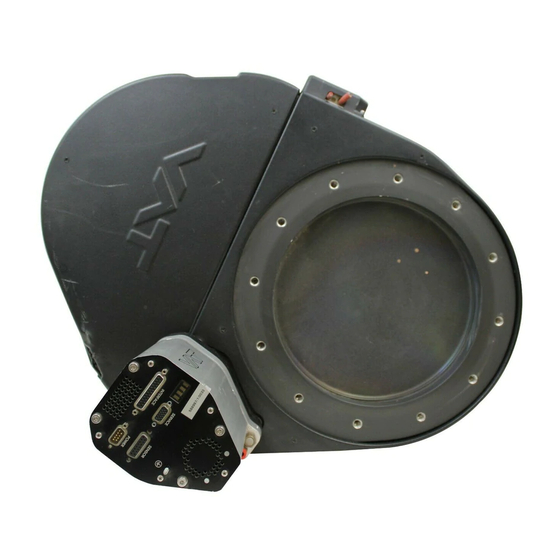
Sample picture
600773EA
Edition 2013-02-21
Advertisement
Table of Contents

Related Manuals for VAT 650 Series


Summary of Contents for VAT 650 Series
- Page 1 Installation, Operating & Maintenance Instructions Pendulum control & isolation valve with DeviceNet interface Series 650 DN 160 mm (I.D. 6") This manual is valid for the valve ordering number(s): 65044-PACQ-0002 ® configured with firmware 650P.1E.42 and 264420 (DeviceNet Sample picture 600773EA Edition 2013-02-21...
- Page 2 The VAT firmware may not be used for purposes other than those intended nor is it permitted to make copies of the VAT firmware. In particular, it is strictly forbidden to give copies of the VAT firmware to other people.
-
Page 3: Table Of Contents
Series 650 Contents Description of product ................ 5 Identification of product ....................5 Use of product ......................... 5 Used abbreviations ......................5 Related documents ......................5 Important information ....................... 5 Technical data ......................... 6 1.6.1 Control and actuating unit ................. 6 1.6.2 Valve unit ...................... - Page 4 Series 650 Operation ................... 56 Normal operation ......................56 5.1.1 Local operation ....................57 5.1.2 Remote operation .................... 58 Close valve ........................59 Open valve ........................59 Position control ......................59 Pressure control ......................60 5.5.1 Pressure control operation with 2 sensors ............60 Display information ......................
-
Page 5: Description Of Product
This product is a throttling pendulum valve with isolation functionality. It is intended to use for downstream pressure control applications. Use product for clean and dry vacuum applications only. Other applications are only allowed with the written permission of VAT. Used abbreviations Abbreviation... -
Page 6: Technical Data
DESCRIPTION OF PRODUCT Series 650 Technical data 1.6.1 Control and actuating unit Data Input voltage +24 VDC (±10%) @ 0.5 V pk-pk max. [connector: POWER] Power consumption 96 W [connector: POWER] Power input (DeviceNet®) 3 W max. (from DeviceNet®) [DeviceNet® connector] Sensor power supply output ±15 VDC (±5%) / 1000 mA max. -
Page 7: Valve Unit
Series 650 DESCRIPTION OF PRODUCT 1.6.2 Valve unit Description 1 × 10E-8 mbar to 1.2 bar (abs) Pressure range at 20 C 1 × 10E-9 mbar l/s Leak rate to outside at 20 C 1 x 10E-9 mbar l/s Leak rate valve seat at 20 C Cycles until first service 200‟000 (unheated and under clean conditions) - Isolation cycles (open - closed - open) -
Page 8: Safety
SAFETY Series 650 Safety Compulsory reading material Read this chapter prior to performing any work with or on the product. It contains important information that is significant for your own personal safety. This chapter must have been read and understood by all persons who perform any kind of work with or on the product during any stage of its serviceable life. -
Page 9: Personnel Qualifications
Series 650 SAFETY Personnel qualifications WARNING Unqualified personnel Inappropriate handling may cause serious injury or property damage. Only qualified personnel are allowed to carry out the described work. Safety labels Label Part No. Location on valve On protective foil covering of T-9001-156 valve opening 600773EA... -
Page 10: Design And Function
DESIGN AND FUNCTION Series 650 Design and Function Design Plate seal Integrated controller Body seal Rotary feed through seals Shaft feed through seals Pendulum plate Bonnet seal Sealing ring Actuator 10/94 Edition 2013-02-21 600773EA... -
Page 11: Function
Series 650 DESIGN AND FUNCTION Function The valve plate acts, due to its pendulum motion, as a throttling element and varies the conductance of the valve opening. The integrated controller calculates the required plate position to achieve the set point pressure. Actuation is performed by a stepper motor. An encoder monitors the position. This principle ensures fast and accurate process pressure control. -
Page 12: Pressure Control System Overview And Function
DESIGN AND FUNCTION Series 650 3.2.1 Pressure control system overview and function Vacuum pressures are always absolute pressures unless explicitly specified as pressure differences. Valve Process chamber Gas inlet Pressure sensor(s) Sensor cable Controller and actuator Seff Cable to remote control unit Cable to power supply HV Pump Q / p... -
Page 13: Principle Of A Pressure Control System
Series 650 DESIGN AND FUNCTION 3.2.1.1 Way of operation The controller compares the actual pressure in the process chamber given by the pressure sensor with the preset pressure. The controller uses the difference between actual and set pressure to calculate the correct position of the control valve. The controller drives the control valve into the correct position and the actual pressure again equals the set pressure. -
Page 14: Installation
Make sure that the supplied products are in accordance with your order. Inspect the quality of the supplied products visually. If it does not meet your requirements, please contact VAT immediately. Store the original packaging material. It may be useful if products must be returned to VAT. -
Page 15: Installation Into The System
Series 650 INSTALLATION Installation into the system WARNING Valve opening Risk of serious injury. Human body parts must be kept out of the valve opening and away from moving parts. Do not connect the controller to power before the valve is installed complete into the system. -
Page 16: Installation Space Condition
INSTALLATION Series 650 Mount valve to a clean system only. 4.2.1 Installation space condition Install the valve with integrated controller with space for dismantling and air circulation as shown in figure below. 100 mm 50 mm 16/94 Edition 2013-02-21 600773EA... -
Page 17: Connection Overview
Series 650 INSTALLATION 4.2.2 Connection overview System: Valve Process chamber Gas inlet Pressure sensor(s) Sensor cable(s) Controller and actuator Cable to remote control unit Cable to power supply Pump Controller: Ground connection DeviceNet® Interface connector 600773EA Edition 2013-02-21 17/94... -
Page 18: Installation Procedure
8. This valve has a double sealed rotary feedthrough and optionally an intermediate pumping port for the actuator shaft. This port (1/8“ ISO/NPT) could be connected to the vacuum line, see Figure 2 below. 9. This valve may optionally be equipped with a heating device. Connect VAT heating device according to manual of respective heating device. -
Page 19: Tightening Torque
Series 650 INSTALLATION Tightening torque The torque values below are dependent on many factors, such as materials involved, surface quality, surface treatment, and lubrication. The torques below are valid if immersion depth of the mounting screws is at least once the thread diameter (min. 1d), and the friction coefficient of the screw-flange connection ( )/2) is bigger than 0.12. - Page 20 » lbf. 2000 For a combination of both forces (F and M) the values are invalid. Verify that the depth of the mounting screws is min. 1 x thread diameter. Please contact VAT for more information. 20/94 Edition 2013-02-21 600773EA...
-
Page 21: Requirements To Sensor Connection
Series 650 INSTALLATION 4.3.3 Requirements to sensor connection To achieve fast and accurate pressure control a fast sensor response is required. Sensor response time: < 50ms. The sensor is normally connected to the chamber by a pipe. To maintain that the response time is not degraded by this connection it needs to meet the following requirements: Inner diameter of connection pipe: >... -
Page 22: Ground Connection
INSTALLATION Series 650 4.4.1 Ground connection Recommendation for ground strap between controller ground and system chassis. Material B1 (min.) B2 (min.) d1 ( ) d2 ( ) (Length max.) copper tinned 200 mm 25 mm 25 mm 4.5 mm customized Recommended torque: 1,3…1,7Nm System Ground strap... -
Page 23: Sensor Supply Concepts
Series 650 INSTALLATION 4.4.2 Sensor supply concepts This valve offers 3 alternative concepts to supply the sensor(s) with power. This depends on the sensor type and valve version that is used. This valve is available with an optional sensor power supply module (SPS) that converts 15 VDC from the 24 VDC. -
Page 24: Power And Sensor Connection ( 15 Vdc Sensors) With Opt. Sps Module
INSTALLATION Series 650 4.4.3 Power and sensor connection ( 15 VDC sensors) with opt. SPS module [650 . . - . . A . - ../ 650 . . - . . C . - ..versions recommended] 4.4.3.1 Sensor power wiring via controller Pins 4 and 8 must be... -
Page 25: Devicenet® Interface Connection
Series 650 INSTALLATION 4.4.4 DeviceNet® interface connection Connector type: Micro-style male (5 pin), connector is shown on panel refer to chapter «Installation into the system». At valve controller DeviceNet® cable Name Wire color Description Drain Bare Shield DeviceNet® power supply + Black DeviceNet®... -
Page 26: Logic I/O
INSTALLATION Series 650 4.4.5 LOGIC I/O This interface allows for remote operation by means of a command set based on the DeviceNet protocol. In addition there is a digital input and a digital output. Digital input may only be operated by a switch. Active digital input has: higher priority than DeviceNet commands higher priority than Local commands... -
Page 27: Service Port Connection
You can use our Software (freeware) 'Control Performance Analyzer' which can be downloaded from: http://www.vatvalve.com/customer-service/informations-and-downloads/control-performance-analyzer. Alternatively the VAT Service Box2 can be connected to the service port for setup and local operation. The service port is not galvanic isolated. Therefore we recommend using this only for setup, testing and maintenance and not for permanent control. -
Page 28: Initial Operation
INSTALLATION Series 650 Initial operation 4.5.1 Setup procedure To enable the valve cluster for pressure control setup steps 1 to 6 must be performed. In case position control is required only it‟s sufficient to perform steps 1 to 4. Setup step Description Turn on external + 24VDC power supply of valve (and external 15 Power up... -
Page 29: Devicenet ® Configuration
® VAT offers valve-related but not general DeviceNet support. Contact us under: devicenet- support@vat.ch 1. The node number is the device address and can be selected by two rotary switches which are on the panel. - Page 30 INSTALLATION Series 650 assignment of I/O data to the corresponding I/O message connections (Polling, Bit Strobe, Change of State) and description of device parameters. The parameters of a device are described in a form which is ® defined by DeviceNet and visualized by a configuration tool.
-
Page 31: Logic I/O Configuration
Series 650 INSTALLATION 4.5.3 LOGIC I/O configuration Default configuration for LOGIC I/O is: Function Mode Input Digital input close valve non inverted enabled Function Mode Output Digital output close non inverted enabled The «LOGIC I/O» Digital input and Digital output can be adjusted. Local operation: Remote operation: („Control View‟, „Control Performance Analyzer‟... -
Page 32: Valve Configuration
INSTALLATION Series 650 4.5.1 Valve configuration Basic valve configuration must be adapted according to application needs. Definition of valve plate position in case of: After power up, default is „close„. Power failure, default is „close„. Only for versions that have Power Fail Option equipped [650 . . - . . C . - . -
Page 33: Zero
Series 650 INSTALLATION 4.5.3 ZERO ZERO allows for the compensation of the sensor offset voltage. When ZERO is performed the current value at the sensor input is equated to pressure zero. In case of a 2 sensor system both sensor inputs will be adjusted. A max. offset voltage of +/- 1.4 V can be compensated. - Page 34 INSTALLATION Series 650 Remote operation: Local operation: (Refer to chapter «Explicit messaging control („Control View‟, „Control Performance commands» resp. «Explicit messaging setup Analyzer‟ or „Service Box 2„) commands» for details) Send EXECUTING (if not yet selected) Select SETPOINT TYPE = position control Go to „Learn / LEARN‟...
-
Page 35: Tuning Of Control Performance
Go to „Tools / Create Diagnostic File‟ in „Control View‟ resp. „Control Performance Analyzer‟ and save file Pressure / flow / gas conditions to be controlled Chamber volume Pumping speed (l/s) and pump type (e.g. turbo pump) System description Problem description Send diagnostic file with and all required information to tuning-support@vat.ch 600773EA Edition 2013-02-21 35/94... - Page 36 INSTALLATION Series 650 4.5.5.1 Gain factor adjustment The gain factor effects: Stability, Response time Default value is 1. Adjustment range is from 0.0001 to 7.5. Higher gain results in: faster response higher over- / undershoot of pressure Lower gain results in: slower response lower over- / undershoot of pressure Adjustment procedure:...
- Page 37 Series 650 INSTALLATION 4.5.5.2 Sensor delay adjustment Sensor delay adjustment effects: Stability Default value is 0. Adjustment range is from 0 to 1.0s. Pipes and orifices for sensor attachment delay response time and so badly impact pressure control stability. By adapting this parameter to the approximate delay time stability problems can be reduced. But control response time will be slowed down by this measure.
- Page 38 INSTALLATION Series 650 4.5.5.3 Setpoint ramp adjustment Setpoint ramp effects: Undershoot of pressure, Response time Default value for Setpoint Ramp is 1. Adjustment range for Setpoint Ramp is from 0 to 10 s. This parameter defines the time that is used to decrease / raise pressure between 2 setpoints. Especially in pressure decrease situations at low flows pressure response can be improved much by adapting setpoint ramp time.
- Page 39 Series 650 INSTALLATION 4.5.5.4 Valve speed adjustment Valve speed effects: Response time Default value is 1000. Adjustment range is from 1 to 1000. This parameter effects valve plate actuating speed. Speed adjustment is effective for PRESSURE CONTROL and POSITION CONTROL. Normally best pressure control response is achieved with max.
-
Page 40: Devicenet Interface Commands
INSTALLATION Series 650 DeviceNet interface commands 4.6.1 Assembly objects Factory default assemblies are: Input assembly 3 / Output assembly 8 Number Type Composition [number of data bytes] EXCEPTION STATUS Input PRESSURE [2] or [4] POSITION [2] or [4] EXCEPTION STATUS Input PRESSURE [2] or [4]... -
Page 41: Assembly Object Bit Map
Series 650 INSTALLATION 4.6.2 Assembly object bit map This is an example based on output assembly 8 and input assembly 3 to illustrate bit map. DATA TYPE in this example is signed integer. 4.6.2.1 Output assembly Assembly Type Byte Bit7 Bit6 Bit5 Bit4... - Page 42 INSTALLATION Series 650 4.6.2.2 Input assembly Instance Type Byte Bit7 Bit6 Bit5 Bit4 Bit3 Bit2 Bit1 Bit0 EXCEPTION STATUS PRESSURE low byte Input PRESSURE high byte POSITION low byte POSITION high byte EXCEPTION STATUS will respond with one out of below selections, see also «Explicit messaging inquiry commands».
-
Page 43: Explicit Messaging Control Commands
Series 650 INSTALLATION 4.6.3 Explicit messaging control commands Service Service Command Service Code Class ID Instance ID Attribute ID data length data field ® (DeviceNet term (number of bytes) if deviant) Description This command changes the valve to executing state. EXECUTING must to be selected to enable for all executing commands such EXECUTING as control mode, close valve and open valve. - Page 44 INSTALLATION Series 650 Service Service Command Service Code Class ID Instance ID Attribute ID data length data field ® (DeviceNet term (number of bytes) if deviant) Description 2 or 4 2 or 4 POSITION SETPOINT position setpoint according to selected DATA TYPE, 0 (closed) … 10’000 (open) This command transfers/reads the position setpoint to/from the valve.
-
Page 45: Explicit Messaging Inquiry Commands
Series 650 INSTALLATION 4.6.4 Explicit messaging inquiry commands Service Service Command Service Code Class ID Instance ID Attribute ID data length data field ® (DeviceNet term (number of bytes) if deviant) Description VALVE CLOSED This command returns: CHECK valve is not closed (discrete input 1) valve is closed VALVE... - Page 46 INSTALLATION Series 650 Example of PRESSURE and SENSOR READING allocation: High range sensor 1 Torr PRESSURE SENSOR 1 READING 0 – 10’000 0 – 10’000 Low range sensor 100 mTorr SENSOR 2 READING 0 – 10’000 0 mTorr Above picture shows a 2 sensor system. In this configuration sensor 2 covers low range (100 mTorr) and sensor 1 covers high range (1 Torr).
- Page 47 Series 650 INSTALLATION Service Service Command Service Code Class ID Instance ID Attribute ID data length data field ® (DeviceNet term (number of bytes) if deviant) Description This command returns the status of the LEARN procedure. The status is binary coded. Explanation: (LSB) 0 0 = LEARN not running...
- Page 48 INSTALLATION Series 650 Service data length Service Command Service Code Class ID Instance ID Attribute ID (number of data field (DeviceNet® term bytes) if deviant) Description self test idle DEVICE STATUS 1 self test exception executing abort This command returns the device status. This command returns the device status.
- Page 49 Series 650 INSTALLATION Service Service Command Service Code Class ID Instance ID Attribute ID data length data field ® (DeviceNet term (number of bytes) if deviant) Description Table with EXCEPTION DETAIL ALARM resp. EXCEPTION DETAIL WARNING bits. Exception / Failure / Error (except for detail size bytes) Data Bit 7 Bit 6...
- Page 50 INSTALLATION Series 650 Service data length Service Command Service Code Class ID Instance ID Attribute ID (number of data field (DeviceNet® term bytes) if deviant) Description THROTTLE CYCLE This command returns the number of throttle cycles. Data type is unsigned long integer. A COUNTER movement from max.
-
Page 51: Explicit Messaging Setup Commands
Series 650 INSTALLATION 4.6.5 Explicit messaging setup commands Service Service Command Service Code Class ID Instance ID Attribute ID data length data field ® (DeviceNet term (number of bytes) if deviant) Description signed integer DATA TYPE floating point This command defines the data type for PRESSURE, SENSOR READING, OFFSET and POSITION. - Page 52 INSTALLATION Series 650 Command Service Service ® (DeviceNet term Service Code Class ID Instance ID Attribute ID data length data field if deviant) (number of bytes) CHANGE OF STATE / CYCLING INPUT input assembly object number (3, 4, 5, 13, 14, 100, 101) This command configures resp.
- Page 53 Series 650 INSTALLATION Command Service Service ® (DeviceNet term Service Code Class ID Instance ID Attribute ID data length data field if deviant) (number of bytes) no sensor 1 sensor operation (sensor 1 input) 2 sensor operation with automatic changeover (low range = sensor 2 input, high range = sensor 1 input) 1 sensor operation (sensor 2 input) 2 sensor operation with automatic changeover...
- Page 54 INSTALLATION Series 650 Command Service Service ® (DeviceNet term Service Code Class ID Instance ID Attribute ID data length data field if deviant) (number of bytes) 2 or 4 LEARN learn pressure limit according to selected DATA TYPE, nominal pressure range is 0 … 10’000 (sensor full scale) but it may be scaled, PRESSURE LIMIT (calibration scale) refer also to command GAIN for details.
- Page 55 Series 650 INSTALLATION Command Service Service ® (DeviceNet term Service Code Class ID Instance ID Attribute ID data length data field if deviant) (number of bytes) 0 = 0.10, 1 = 0.13, 2 = 0.18, 3 = 0.23, 4 = 0.32, 5 = 0.42, 6 = 0.56 PID CONTROLLER 7 = 0.75, 8 = 1.00, 9 = 1.33, 10 = 1.78, 11 = 2.37, 12 = 3.16, 13 = 4.22 GAIN FACTOR...
-
Page 56: Operation
OPERATION Series 650 Operation WARNING Unqualified personnel Inappropriate handling may cause serious injury or property damage. Only qualified personnel are allowed to carry out the described work. WARNING Valve opening Risk of serious injury. Human body parts must be kept out of the valve opening and away from moving parts. Do not connect the controller to power before the valve is installed complete into the system. -
Page 57: Local Operation
Local operation means that the valve is operated via the service port using a computer or the Service Box 2. When using a computer, a service cable and a software from VAT is required. You can use our Software (freeware) 'Control Performance Analyzer' which can be downloaded from: http://www.vatvalve.com/customer-service/informations-and-downloads/control-performance-analyzer. -
Page 58: Remote Operation
OPERATION Series 650 5.1.2 Remote operation This product is equipped with a DeviceNet interface to allow for remote operation. See section «DeviceNet interface» for details. 'Control Performance Analyzer' software or 'Service Box 2' may be used for monitoring during remote control. 'Control Performance Analyzer' software 'Service Box 2' In case „Control Performance Analyzer‟... -
Page 59: Close Valve
Series 650 OPERATION Close valve Local operation: Remote operation: („Control View‟, „Control Performance Analyzer‟ or (Refer to chapter «Explicit messaging control „Service Box 2„) commands» for details) Send EXECUTING (if not yet selected) Send SETPOINT TYPE Push CLOSE button = position control Send CONTROL MODE for position = close valve Open valve... -
Page 60: Pressure Control
OPERATION Series 650 Pressure control To prepare valve for PRESSURE CONTROL perform complete «Setup procedure». The valve has parameters that may be modified to tune pressure control performance. Refer to «Tuning of control performance». The included PID controller controls the chamber pressure according to the pressure setpoint by means of the valve position. -
Page 61: Display Information
Series 650 OPERATION Display information There is a 4 digit display located on the panel. It displays configuration, status and position information. For details see following tables. 1 2 3 4 Display 5.6.1 Power up Description Digit 1 Digit 2 Digit 3 Digit 4 At first all dots are illuminated then... -
Page 62: Operation
OPERATION Series 650 5.6.2 Operation Description / Mode Digit 1 Digit 2 Digit 3 Digit 4 PRESSURE CONTROL mode POSITION CONTROL mode Valve closed Valve open 0 . . . 100 = valve position (%, 0 = closed / 100 = open) HOLD (position frozen) activated ZERO running LEARN running... -
Page 63: Operation During Power Up
650 . . - . .U . - ../ 650 . . - . .W . - ..Valve will close or open depending on valve configuration. Default is close. Provide that battery pack of the VAT controller is charged. Display indicates F. All parameters are stored in a power fail save memory. -
Page 64: Operation Under Increased Temperature
OPERATION Series 650 Operation under increased temperature CAUTION Hot valve Heated valve may result in minor or moderate injury. Do not touch valve and heating device during operation. Once heating is switched off (valve and system) await until the valve is cooled down complete before doing any work. -
Page 65: Trouble Shooting
TROUBLE SHOOTING Series 650 Trouble shooting Failure Check Action No dots lighted on display - 24 V power supply ok? - Connect valve to power supply according to «Electrical connection» and make sure that power supply is working. ® ® Module Status LED is off - DeviceNet power supply ok? - Connect valve to DeviceNet... - Page 66 - No compressed air at output - Contact your local VAT service centre for support. exhaust 1)Priority of pin 14 is higher than pin 13. If pin 14 is connected to ground after pin 13 the valve will close.
- Page 67 TROUBLE SHOOTING Series 650 Failure Check Action Pressure reading is wrong - Sensor(s) connected? - Refer to «Electrical connection». - 2 sensor version present at - Check valve version on page 1. Verify configuration. pressure reading is negative valve controller? Refer to «Setup procedure».
-
Page 68: Maintenance
Before carrying out any maintenance, please contact VAT. It has to be individually decided whether the maintenance can be performed by the customer or has to be carried out by VAT. Please write down the fabrication number of the valve before contact VAT. Refer to chapter «Identification of product»... -
Page 69: Maintenance Procedures
A critical factor influencing the maintenance period is the lifetime of the vacuum grease, being limited under increased temperature. In this case grease will separate to PTFE and oil. The oil may flow and contaminate the valve parts. VAT can give the following recommendations for preventive maintenance: Replacement of unheated heated 80 °C... -
Page 70: Replacement Of Isolation Seals And Cleaning
Open end wrench 13 mm Clean room wiper O-ring removal tool (see chapter: Accessories) Isopropyl alcohol VAT cleaning tool (see chapter: Accessories) Electrical power and compressed air is required to perform steps 2 to 9 during disassembly respectively 9 to 2 during assembly. Description Required tool Vent both valve chambers. - Page 71 VAT cleaning tool in an ultrasonic bath. Isopropyl alcohol 12. Clean out valve body with alcohol. Use VAT cleaning tool or an Clean room wiper appropriate non metal tool with a cloth to enter valve body. Do not enter valve body with hands! 13.
- Page 72 Series 650 Description Required tool Apply grease deposit Vacuum grease on this side VAT cleaning tool 17. Clean the valve body. Isopropyl alcohol 18. Reassembly the valve in reverse order, step 9…3. Isopropyl alcohol 19. Clean the valve sealing surface.
-
Page 73: Replacement Of Actuator Shaft Seals
7.2.2 Replacement of actuator shaft seals 7.2.2.1 Required tools Allen Wrench 2 mm VAT cleaning tool (see chapter: Accessories) Allen Wrench 4 mm Vacuum grease (see chapter: Spare parts) Allen Wrench 5 mm Clean room wiper Open end wrench 13 mm... - Page 74 MAINTENANCE Series 650 Description Required tool 6. With one hand press the [Maintenance button] to lower the unlock sealing ring, with your second hand unlock the sealing ring by pressing the handle. lock 7. Release [Maintenance button]. 8. Remove sealing ring. 9.
- Page 75 Series 650 MAINTENANCE Description Required tool 15. Unfasten all 3 actuator screws and Allen wrench 5 mm remove actuator. 16. Remove actuator shaft seals carefully O-ring removal tool with soft tool. 17. Clean the actuator feed through and Clean room wiper grooves.
- Page 76 MAINTENANCE Series 650 Description Required tool 23. Remove fixation kit and mounting screw for pendulum plate. 24. Clean screw and slightly lubricate Vacuum grease thread. Then reinstall fixation kit. 25. Clean actuator shaft and lubricate it with 0.1 ml vacuum grease. 26.
- Page 77 Series 650 MAINTENANCE Description Required tool Distance D[mm] between bonnet flange surface and pendulum If actuator was replaced, plate. proceed with step 30, otherwise go to step 34. 30. Close valve and check if pendulum plate is in center of flange. Check can be done either visual or by measurement.
-
Page 78: Replacement Of Option Board
MAINTENANCE Series 650 7.2.3 Replacement of Option board NOTICE Electrostatic discharge Electronic components could be damage. All work on the control and actuating unit has to be done under ESD protected environment to prevent electronic components from damage. NOTICE Burned connector pins (spark) Connector pins or electronic parts could damage, if plugged and unplugged under power. - Page 79 Series 650 MAINTENANCE 7.2.3.1 Durability of power fail battery The curves in the graph show the estimated life of Ultra Cap PFO in the worst condition (max. sensor load = 1 A, valve heating temperature = 150 °C). If the SPS is not fully loaded (< 1 A) or heating temperature of valve body is lower than 150 °C, the corresponding life time curve will be somewhere in between the upper and the lower curve.
- Page 80 MAINTENANCE Series 650 7.2.3.2 Retrofit / replacement procedure Top view on control and actuating unit with panel removed: Master board Interface board Option board All boards have a fixed position into control and actuating unit. It is not possible to fit a board in other position as shown in picture above! Do not try out other positions, which maybe destroy the socket of boards! 80/94...
- Page 81 Series 650 MAINTENANCE 7.2.3.3 Needed tools Open end wrench 10 mm Pozidriv screw driver size 1 Open end wrench 4.5mm Description Required tool Write down the «NODE ADDRESS» and «DATA RATE» in case of Interface board Ballpoint replacement. Remove female screw locks from POWER Open end wrench 4.5 and SENSOR connectors.
- Page 82 MAINTENANCE Series 650 Description Required tool Lift the panel carefully. Pull out the option board a little. Push the connector release (1) a little down and disconnect fan cable (2) from option board. Push the connector release (1) a little down and disconnect DeviceNet cable (2) from interface board.
- Page 83 Series 650 MAINTENANCE Description Required tool 10. Remove or replace master board. 11. Remove or replace option board. 12. Insert master board and interface board in reverse order as disassembled at correct positions (see steps 9 to 8). 13. Reconnect DeviceNet cable to interface board (see step 7).
-
Page 84: Repairs
Series 650 Repairs Repairs may only be carried out by the VAT service staff. In exceptional cases, the customer is allowed to carry out the repairs, but only with the prior consent of VAT. Please contact one of our service centers. You will find the addresses on our website www.vatvalve.com. -
Page 85: Dismounting And Storage
Series 650 DISMOUNTING AND STORAGE Dismounting and Storage WARNING Unqualified personnel Inappropriate handling may cause serious injury or property damage. Only qualified personnel are allowed to carry out the described work. Dismounting NOTICE Contamination Gate and other parts of the valve must be protected from contamination. Always wear clean room gloves when handling the valve. -
Page 86: Storage
DISMOUNTING AND STORAGE Series 650 Storage NOTICE Wrong storage Inappropriate temperatures and humidity may cause damage to the product. Valve must be stored at: – relative humidity between 10% and 70% – temperature between +10 °C and +50 °C – non-condensing environment NOTICE Inappropriate packaging Product may get damaged if inappropriate packaging material is used. -
Page 87: Packaging And Transport
If products are radioactively contaminated, the VAT form «Contamination and Radiation Report» must be filled out. Please contact VAT in advance. If products are sent to VAT in contaminated condition, VAT will carry out the decontaminating procedure at the customer's expense. -
Page 88: Transport
10.2 Transport NOTICE Inappropriate packaging Product may get damaged if inappropriate packaging material is used. Always use the original packaging material and handle product with care. VAT disclaims any liability for damages resulting from inappropriate packaging. 88/94 Edition 2013-02-21 600773EA... -
Page 89: Disposal
Series 650 DISPOSAL Disposal WARNING Unqualified personnel Inappropriate handling may cause serious injury or property damage. Only qualified personnel are allowed to carry out the described work. 600773EA Edition 2013-02-21 89/94... -
Page 90: Spare Parts
«Identification of product». This is to ensure that the appropriate spare parts are supplied. VAT makes a difference between spare parts that may be replaced by the customer and those that need to be replaced by the VAT service staff. -
Page 91: Valve Unit With Seals And Grease
101570-01 Sealing ring 207518 Syringe of vacuum grease 206792 (2ml), 206793 (5ml) Use only spare parts manufactured by VAT to assure safe and reliable operation All “ All “Item“ refer to chapter «Drawing» 12.1.2 Control and actuating unit Item Description... -
Page 92: Accessories
RS232, RS485 and Logic only) Service Box 2 601BS-29NN-000 Control panel (rack-mount version of 602BS-29LE-000 Service Box 2) O-ring removal tool 234859 VAT valve cleaning tool 305709 12.1.3.1 Centering ring with Viton o-ring Description DN 160 / 6” Valve size Product ordering number 65044 - . -
Page 93: Appendix
APPENDIX Series 650 Appendix No information entered on time. 600773EA Edition 2013-02-21 93/94... - Page 94 Series 650 This page left blank intentionally. 94/94 Edition 2013-02-21 600773EA...
Need help?
Do you have a question about the 650 Series and is the answer not in the manual?
Questions and answers