Table of Contents
Advertisement
Quick Links
Advertisement
Table of Contents

Related Manuals for Alvarado TAS12-EDM


Summary of Contents for Alvarado TAS12-EDM
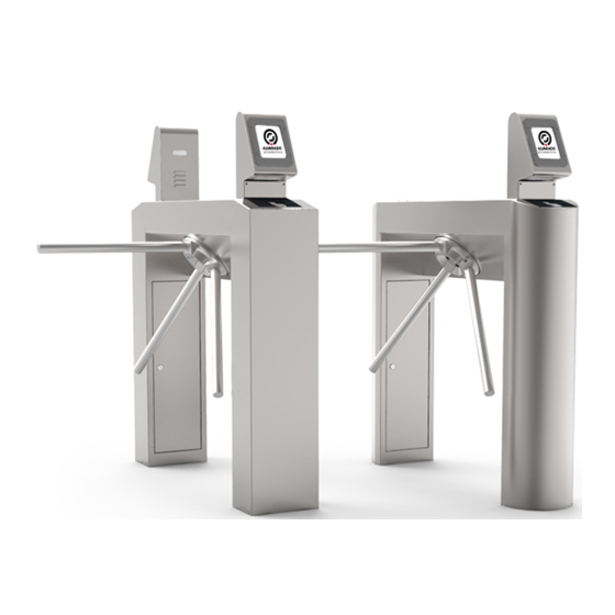
- Page 1 TAS12-EDM & TAS12P-EDM MOTORIZED INTELLIGENT ADMISSION TURNSTILE TAS12P-EDM TAS12-EDM Installation Instructions Alvarado Manufacturing Company, Inc. 12660 Colony Street, Chino, CA 91710 Telephone: +1 (909) 591-8431 Fax: +1 (909) 628-1403 support@alvaradomfg.com www.alvaradomfg.com PUD4005R1-0...
-
Page 2: Table Of Contents
TAS12-EDM & TAS12P-EDM Installation Instructions Contents Contents..................................2 Safety Icons..................................3 Safety Precautions................................3 Tools Required (Fixed Turnstile Installation)........................4 Parts List..................................5 Overview..................................6 Power..................................6 Communication................................. 6 Installation Steps............................... 7 Before you Begin................................7 Site Preparation. -
Page 3: Safety Icons
This symbol is used in this manual to designate useful information for the installer and operator. NOTE Please read these instructions. For questions, please contact Alvarado at +1 (909) 591-8431, Mon. – Fri. 7:00am to 4:00pm PST. Please read this manual completely before installing or operating the product. Safety Precautions WARNING •... -
Page 4: Tools Required (Fixed Turnstile Installation)
TAS12-EDM & TAS12P-EDM Installation Instructions Tools Required (Fixed Turnstile Installation) • Socket Wrench • Torque Wrench (ft-lbs) • Hammer Drill • 9/16" Socket • 5/8" Concrete Drill Bit • Hammer • Shop Vac • Tape Measure • 5/32" Allen Wrench •... -
Page 5: Parts List
This product is shipped with installation hardware. Make sure that no parts are missing or damaged before beginning installation. If parts are missing or damaged, please stop the installation and contact Alvarado. Additional copies of this installation manual can be found at www.alvaradomfg.com. -
Page 6: Overview
(wired or wireless) is dependent on what options were specified during the ordering process, and the type of network used at the host facility. The turnstile will ship pre-configured with the network settings provided to Alvarado during the ordering process. -
Page 7: Installation Steps
TAS12-EDM & TAS12P-EDM Installation Instructions Installation Steps Fixed Installation Portable Installation 1. Anchor the turnstile to the concrete slab. 1. Install the guide rail to the portable base plate. 2. Connect primary power. 2. Mount the TAS12 unit to the turnstile lid. -
Page 8: Site Preparation
TAS12-EDM & TAS12P-EDM Installation Instructions Site Preparation Use only skilled technicians for site preparation and installation of the turnstile using Alvarado’s instructions. Refer to the footprint and plan drawings [Figures 1 & 2] to determine the installation location and conduit requirements. See Appendix A on page 24 for footprint and plan drawings for the Portable Base Turnstile. - Page 9 TAS12-EDM & TAS12P-EDM Installation Instructions Space & Conduit Requirements (cont.) Fig. 3a Fig. 3b Fig. 3c PUD4005R1-0 For Assistance: support@alvaradomfg.com +1 (909) 591-8431 Page 9...
-
Page 10: Anchoring The Turnstile
TAS12-EDM & TAS12P-EDM Installation Instructions Anchoring the Turnstile Fig. 4 1. Using a turnstile lid key, open the turnstile leg access panels [Figure 4]. 2. Using a 9/16" socket wrench, remove the four (4) bolts that secure the temporary wood plate to the turnstile. -
Page 11: Primary Power Wiring Instructions
TAS12-EDM & TAS12P-EDM Installation Instructions Primary Power Wiring Instructions NOTE The following instructions are for fixed turnstile installations only. If you are installing a portable AC-powered or battery-powered unit, please refer to Appendix A - Portable Base Turnstile instructions on page 24. -
Page 12: Tas12 Installation
TAS12-EDM & TAS12P-EDM Installation Instructions TAS12 Installation If you are installing a Dual TAS12 turnstile, the TAS12 units will be labeled ENTRY and EXIT. NOTE It is the responsibility of the installers to ensure the entry and exit TAS12 units are installed in accordance to your project layout. -
Page 13: Tas12 Connection Instructions
TAS12-EDM & TAS12P-EDM Installation Instructions TAS12 Connection Instructions Ensure turnstile power is OFF before connecting TAS12 cabling. NOTE TAS12 Inputs TAS12 cables are routed to the TAS12 mounting location. Depending on the turnstile options ordered, not all wiring instructions may be applicable. -
Page 14: Post-Installation Inspection
TAS12-EDM & TAS12P-EDM Installation Instructions Post-Installation Inspection Perform this post-installation inspection BEFORE powering on the turnstile for the first time. 1. Anchoring (fixed installations only): Verify the anchor bolts are tensioned to 20 ft-lbs. Tighten if necessary. 2. TAS12: Verify the TAS12 mounting screws are tightened. Tighten if necessary. -
Page 15: Power On
TAS12-EDM & TAS12P-EDM Installation Instructions Power On 1. Power on the turnstile by pushing the recessed Fig. 13 power button on the arm side of the turnstile cabinet using the eraser end of a pencil (or similar shaped object). The location of the power button will differ depending on if the turnstile is a right-hand or left- hand unit [Figure 13]. -
Page 16: Perform Tas12 Device Tests
TAS12-EDM & TAS12P-EDM Installation Instructions Perform TAS12 Device Tests Fig. 15 NOTE The use of a stylus is recommended for all touch screen operations. 1. Make sure the turnstile is online and communicating with the GateLink10 server. 2. Tap the TAS12 screen three times to bring up the Operator Login Screen [Figure 15]. - Page 17 TAS12-EDM & TAS12P-EDM Installation Instructions Perform TAS12 Device Tests (cont.) Fig. 17 1. Press the button for the device test to be performed: • Print Ticket - Press this button to print a test ticket from the integrated thermal printer (TAS12P-EDM only).
-
Page 18: Scan A Sample Barcode Ticket
TAS12-EDM & TAS12P-EDM Installation Instructions Scan a Sample Barcode Ticket Fig. 18 Scan a sample barcode to activate the turnstile. Each sample barcode is good for one passage only. 1. To scan, place the barcode on the blackout pad facing up towards the imager [Figure 18]. The imager will beep when the ticket has been scanned. -
Page 19: Test Drop Arm Operation
TAS12-EDM & TAS12P-EDM Installation Instructions Test Drop Arm Operation The turnstile is designed for the horizontal arm to drop upon loss of power. To test drop-arm functionality: Fig. 20 1. Power OFF the turnstile 2. Verify the horizontal arm drops allowing free egress [Figure 20]. -
Page 20: Test Key Override Operation.(Optional)
TAS12-EDM & TAS12P-EDM Installation Instructions Test Key Override Operation (Optional) Key Override switches are provided to manually place the turnstile in one of three passage modes: Free Passage, Controlled Passage, and No Passage. There is one key override switch per rotation direction. The key switches are located on the underside of the of the turnstile adjacent to the head and arms [Figure 21]. -
Page 21: Test The Local Counter (Optional)
TAS12-EDM & TAS12P-EDM Installation Instructions Test the Local Counter (Optional) The battery-powered LCD counter is used to count turnstile rotations. Each rotation of the turnstile arm generates a count. One counter is required per direction of rotation. 1. Place the turnstile in Free Passage Mode using the Key Override. -
Page 22: Post-Installation Checklist
Check that the mounting bolts and screws are secure and tightened per the requirements in this manual. 7. Finish Stainless Steel – Wipe down the entire turnstile with a damp cloth or used the Alvarado recommended commercial products (see Operation and Maintenance Instructions). -
Page 23: Troubleshooting
TAS12-EDM & TAS12P-EDM Installation Instructions Troubleshooting This basic troubleshooting section is provided to aid installers with the most commonly encountered installation problems. If you require more troubleshooting assistance, see the Operations and Maintenance Instructions. Problem Possible Cause Solution After powering ON the turnstile, the TAS12 No primary power to the Verify power is ON at the circuit breaker. -
Page 24: Appendix A - Portable Base Turnstile
TAS12-EDM & TAS12P-EDM Installation Instructions Appendix A - Portable Base Turnstile These supplemental instructions cover installation steps specific to portable base models only. When the installation is complete, proceed to the Post-Installation Functions Check located on page 14. Portable Base Plate Illustrated Parts List... -
Page 25: Installing Neutrik Connector To Ac Cord
TAS12-EDM & TAS12P-EDM Installation Instructions Installing Neutrik Connector to AC Cord NOTE Portable Base Turnstile units do not ship with power cables. Instead, each turnstile ships from the factory with a disassembled Neutrik connector. Use the connector to create power cables per your facility’s requirements and specifications. -
Page 26: Connecting Ac Power To The Portable Turnstile (Ac-Powered Option Only)
TAS12-EDM & TAS12P-EDM Installation Instructions Installing Neutrik Connector to AC Cord (cont.) Fasten bushing by means of a fork wrench 7/8” W rench size 7/8" (SW22) (SW 22), min. Torque 2.5 Nm (1.8 lb-ft). Torque Value 2.5 Nm FINISH ED p ow erCO N... -
Page 27: Charging The Portable Turnstile (Battery-Powered Option Only)
TAS12-EDM & TAS12P-EDM Installation Instructions Charging the Portable Turnstile (Battery-Powered Option Only) Fig. A6 Power OFF the turnstile prior to charging the batteries. To charge the turnstile [Figure A6]: Lift charge receptacle cover. Plug the extension cord into the turnstile AC inlet. - Page 28 TAS12-EDM & TAS12P-EDM Installation Instructions Portable Base Turnstile - Plan, Elevation and Footprint Drawing Fig. A8 Fig. A9 Fig. A10 Page 28 For Assistance: support@alvaradomfg.com +1 (909) 591-8431 PUD4005R1-0...
- Page 29 TAS12-EDM & TAS12P-EDM Installation Instructions Revision History Revision Date Author Description 2/24/2017 A. Flores Original document. PUD4005R1-0 For Assistance: support@alvaradomfg.com +1 (909) 591-8431 Page 29...
- Page 30 12660 Colony Street, Chino, CA 91710 Telephone: (909) 591-8431 Fax: (909) 628-1403 support@alvaradomfg.com www.alvaradomfg.com © 2017 Alvarado Manufacturing Company, Inc. This work may not be reproduced, published or redistributed, in whole or in part, without the express prior written permission of Alvarado.
Need help?
Do you have a question about the TAS12-EDM and is the answer not in the manual?
Questions and answers