Table of Contents
Advertisement
Quick Links
Advertisement
Table of Contents

Related Manuals for Alvarado MST-3


Summary of Contents for Alvarado MST-3
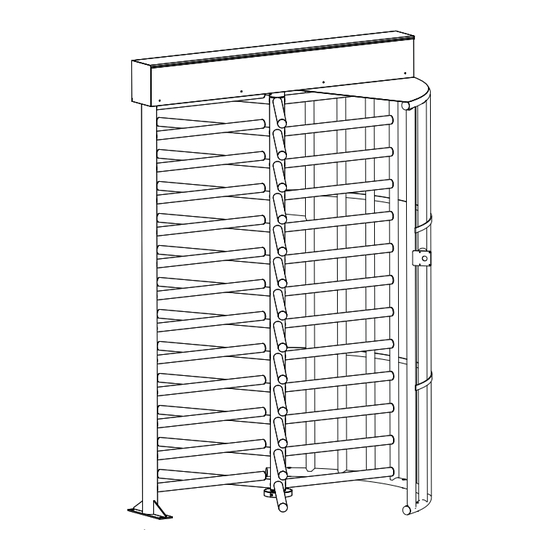
- Page 1 FULL HEIGHT MAXIMUM SECURITY TURNSTILE Installation and Operation Instructions Alvarado Manufacturing Company, Inc. 12660 Colony Street, Chino, CA 91710 Toll Free: (800) 423-4143 Fax: (909) 628-1403 information@alvaradomfg.com www.alvaradomfg.com PUD1208R5-9...
-
Page 2: Table Of Contents
Please read these instructions. For questions, please contact Alvarado at (909) 591-8431, Monday – Friday 6:30am to 4:30 PST. Please read this manual completely before installing or operating the product. Page 2 Installation Instructions information@alvaradomfg.com... -
Page 3: Safety Precautions
• Do not modify or alter the turnstile. • Use only Alvarado parts when repairing or maintaining the turnstile. • Ensure that all users are properly trained. SAVE THESE INSTRUCTIONS CE Compliance and Standards This page defi... -
Page 4: Parts List
Alvarado. Alvarado full height turnstiles share common components across models. The parts list below is NOTE for the MST-3 and MST-6X models only. Reference appendix A-D to see alternate components used on other models. MST Illustrated Parts List... -
Page 5: Before You Begin
Before You Begin This manual focuses on the installation of Alvarado full height turnstiles, using the MST and MSTX as the basis of instruction. Most steps are identical across models. Differences in components or installation process are called out, as applicable. -
Page 6: Installation Instructions
Install the turnstile on a 6' x 6' (min.) level concrete slab. The slab must be a minimum of 4" thickness. The turnstile may only be installed on concrete. Do not install the turnstile on asphalt. DIMENSIONS SHOWN ARE FOR MST-3 and MST-6X MODELS. SEE APPENDIX A-D FOR OTHER MODELS. Fig. 1 Fig. - Page 7 MST Installation Instructions Bottom Bearing Plate Installation Place the bottom bearing plate over the turnstile and Roto intersecting lines. Mark the center location of all four anchor holes for the bottom bearing plate (Figure 3). Set aside the Fig. 3 Fig.
- Page 8 MST Installation Instructions Yoke Installation NOTES Do not use a single Yoke as a template when multiple turnstiles are installed, as Yoke dimensions may vary slightly from Yoke to Yoke. Fig. 7 Fig. 7 STEPS AND DIMENSIONS SHOWN NOTE Yoke Center ARE FOR MST MODELS.
-
Page 9: Roto Installation
MST Installation Instructions OV Installation STEPS AND DIMENSIONS SHOWN NOTE ARE FOR MST MODELS. SEE APPENDIX A-D FOR OTHER MODELS. Reconfi rm the centerline location for the OV (Figure 11). While holding the OV in place, use a pencil and mark the Fig. -
Page 10: Top Channel Installation
MST Installation Instructions Roto Installation (Cont) Apply grease, as instructed in the Roto Installation note on the previous page. Lower the Roto, bottom bearing fi rst, into the bottom bearing plate (Figure 16). Wipe away any excess grease. When complete, refer to Figure 17 for correct orientation. Fig. - Page 11 MST Installation Instructions Top Channel Installation (Cont) With the help of two assistants, lift the Top Channel up and over Roto, Yoke and OV (Figure 19). DANGER Be sure that the feeder wire and/or any access Fig. 19 Fig. 19 control pad wiring is out of the way and is not caught between the Top Channel and the Yoke, Roto or OV, as this may damage the wires.
-
Page 12: Guard Plate Installation
MST Installation Instructions Top Channel Installation (Cont) Fig. 21 Fig. 21 ½" Nut and Power Switch Lock Washer Fuse ½" x 1½" Hex Head Bolt ½" Nut and Lock Washer ½" x 2¾" Hex Head Bolt The Top Channel mounting holes are located at each end of the Top Channel (Figure 21). A. -
Page 13: Bearing Cover Installation
MST Installation Instructions Bearing Cover Installation NOTE For illustration and clarity purposes only, the bearing cover illustrations are shown without the surrounding sections. Fig. 23 Fig. 23 Top Bearing Cover Installation Top Bearing Place the two halves of the top bearing cover over Covers the top bearing and align the mounting holes. -
Page 14: Final Mechanical Installation Steps
MST Installation Instructions Final Mechanical Installation Steps NOTE Be sure the Guard Plate and the Yoke are aligned properly and fl ush before performing the following step(s). Be sure that the turnstile is level before performing the following step(s). If it is not level, use shims as needed. Ensure that all mounting hardware is tightened. -
Page 15: Electrical Wiring Instructions
MST Installation Instructions Electrical Wiring Instructions WARNING At this time, run power to the unit (if you have not already done so). Use a licensed electrician to perform this procedure. NOTES For electric models, power wires can be run through the vertical tube of the OV. Conduit may also be attached directly to the Top Channel cover. - Page 16 MST Installation Instructions Turnstile Control Board Layout Fig. 29 Fig. 29 CCW CW X 5 R G Y X 5 R G Y LEGEND Item Name CCW Test Activation Switch (SW7) Access Control Activation - CCW Access Control Activation CW CW Activation Test Switch (SW6) DIP Switches (SW4) Green LED...
- Page 17 Left Hand/Counter Clockwise Direction be used to output a “count” signal to an external system such as Count Alvarado’s GateWatch or to provide feedback to the access control system that a turnstile rotation has taken place. Confi rmation signal upon turnstile rotation - Common dry contact connection for CNT count signal output.
- Page 18 “count” signal to an external system such as Count Direction Alvarado’s GateWatch or to provide feedback to the access control system that a turnstile rotation has taken place. Confi rmation signal upon turnstile Common dry contact connection for CNT count signal output. See J3...
-
Page 19: User Activation And Passage Instructions
120° rotation. Taking long steps could cause the trailing arm section to strike your heels. Heel and arm guards are an option that can be purchased from Alvarado. Step completely out of the turnstile. CAUTION If a patron does not complete the full rotation before the predefi... -
Page 20: Post-Installation Checklist
Top channel cover is in place. Finish Stainless Steel (Uncoated) – wipe down the entire turnstile with clean water or use the Alvarado recommended commercial products (see Cleaning and Maintenance Section). Stainless Steel (units with optional coating) – wipe down entire turnstile with clean water. -
Page 21: Troubleshooting
The steps contained in this Troubleshooting section are the most common issues that may arise during the operation of the unit. If the provided steps do not resolve the issue, please contact Alvarado Technical Support (909-591-8431). The built-in key locks provide override functionality. Verify that locks are not in the override position before performing any troubleshooting procedures. - Page 22 MST Installation Instructions Troubleshooting (Cont) Fail-safe direction will not unlock Power Issues Cause Solution Reference Green LED is OFF 1. Verify that the power switch is in the ON position and that primary power is Fig. 21A - Power switch provided to the turnstile.
- Page 23 MST Installation Instructions Troubleshooting (Cont) Fail-safe direction will not re-lock (cont) Electronic Issues Cause Solution Reference Optical sensors are dirty Use an alcohol-moistened Q-tip to clean the optical sensor(s) and retest. Fig. 32 (M) Optical sensors misaligned Verify that cam fl ag passes freely through the optical sensor assembly. Fig.
- Page 24 MST Installation Instructions Troubleshooting (Cont) Fail-lock direction will not re-lock Power Issues Cause Solution Reference Green LED is OFF 1. Verify that the power switch is in the ON position and that primary power is Fig. 21A - Power provided to the turnstile. switch is located on the J-box inside the Top Channel.
- Page 25 MST Installation Instructions Troubleshooting (Cont) Self-Centering Adjustment Fig. 33 Fig. 33 4.00”* Centering Shoe Tension Springs 9/16” Wrench Back Plate Tension Spring Lock Bolt Back Plate Lock Nut Lock Nut Lock Bolt 9/16” Socket and Socket Wrench Dimension shown with Roto in the “home” position (no-load on tension springs). Tools: 9/16”...
-
Page 26: Cleaning And Maintenance
MST Installation Instructions Cleaning and Maintenance The frequency of interior maintenance will depend on how often the turnstile is used, the type of personnel using the turnstile and the environment. Installed turnstiles should be inspected once during the fi rst 30 days after installation. Thereafter, follow the maintenance schedule on the following pages. - Page 27 Rusted surfaces and even damaged pitted surfaces can generally be cleaned with the MAAS product but highly damaged areas may require chemical passivation. To chemically passivate stainless steel, Alvarado recommends the use of a citric acid product, CitriSurf2310, available from Stellar Solutions (www.citrisurf.com). This product is especially formulated to clean and passivate stainless steel and can be used in the fi...
-
Page 28: Lubrication
The solenoid is designed for "dry" operation only. NOTE: Use only Alvarado springs and only the springs designated for the location and use purpose. Turnstile springs are not interchangeable and should be used in designated locations only. - Page 29 MST Installation Instructions Lubrication (Cont) Fig. 35 Fig. 35 Springs (Figure 35) Lubricate spring contact points with Tri-Flow. Place lubricant on spring body by adding 1 drop on contact points. DO NOT lubricate the silver solenoid plunger arm. Lock Arm Return Spring Solenoid...
-
Page 30: Appendix A - Cpst Installation
CPST Installation Instructions MST Installation Instructions Appendix A - CPST Installation These instructions are for installing the Yoke section of the CLST. When complete, please refer back to the "OV Installation" section. CPST Illustrated Parts List Yoke Roto (Qty 1) (Qty 1) (Qty 1) Yoke Mounting Channel... - Page 31 MST Installation Instructions CPST Installation Instructions Yoke Installation Determine the installation location for the Yoke. Identify the threaded aluminum block at the top of each section. (Figure A1). Fig. A2 Fig. A2 Push the two sections together (Figure A2). Threaded NOTE Aluminum Block Prior to drilling the anchor bolt holes, use a tape measure and...
- Page 32 CPST Installation Instructions MST Installation Instructions Yoke Installation (Cont) Using a ⅝" concrete drill bit, drill an anchor hole 3" in depth (Figure A6). Repeat this step for the remaining mounting holes. Fig. A6 Fig. A6 NOTES The anchor hole(s) must be clean before installing the anchor bolt(s).
-
Page 33: Appendix B - Clst Installation
CLST Installation Instructions MST Installation Instructions Appendix B - CLST Installation These instructions are for installing the Yoke section of the CLST. When complete, please refer back to the "OV Installation" section. CLST Illustrated Parts List Yoke Roto (Qty 1) (Qty 1) (Qty 1) Yoke Mounting Channel... -
Page 34: Appendix C - Fmst Installation
FMST Installation Instructions MST Installation Instructions Appendix C - FMST Installation These instructions are for installing the Yoke section of the FMST. When complete, please refer back to the "OV Installation" section. FMST Illustrated Parts List Yoke Roto (Qty 1) (Qty 1) (Qty 1) Determine where the turnstile will be installed. -
Page 35: Appendix D - Mst47 Installation
MST Installation Instructions MST47 Installation Instructions Appendix D - MST47 Installation These instructions are for installing the Yoke section of the MST47. When complete, please refer back to the "OV Installation" section. MST47 Illustrated Parts List Yoke Roto (Qty 1) (Qty 1) (Qty 1) Determine where the turnstile will be installed. -
Page 36: Appendix E - Fail-Lock / Fail-Safe Spring And Solenoid Confi Gurations
MST Installation Instructions Appendix E - Fail-lock / Fail-safe Spring and Solenoid Confi gurations Clockwise Fail-lock / Fail-safe Spring and Solenoid Confi gurations - Adjustable Solenoid For use with turnstiles that utilize adjustable solenoid mounting positions. NOTE Fail-safe Fail-lock CW Lock CW Lock (Silver) Fail-safe... - Page 37 MST Installation Instructions Appendix E - Fail-lock / Fail-safe Spring and Solenoid Confi gurations (Cont) Counter-Clockwise Fail-lock / Fail-safe Spring and Solenoid Confi gurations - Adjustable Solenoid For use with turnstiles that utilize adjustable solenoid mounting positions. NOTE Fail-safe Fail-lock Lock Arm (Red) Lock Arm...
- Page 38 MST Installation Instructions Appendix E - Fail-lock / Fail-safe Spring and Solenoid Confi gurations (Cont) Clockwise Fail-lock / Fail-safe Spring and Solenoid Confi gurations - Fixed Solenoid For use with turnstiles that utilize fi xed solenoid mounting positions. NOTE Fail-safe Fail-lock CW Lock CW Lock...
- Page 39 MST Installation Instructions Appendix E - Fail-lock / Fail-safe Spring and Solenoid Confi gurations (Cont) Clockwise Fail-lock / Fail-safe Spring and Solenoid Confi gurations - Fixed Solenoid For use with turnstiles that utilize fi xed solenoid mounting positions. NOTE Fail-safe Fail-lock Lock Arm (Red)
-
Page 40: Appendix F - Key Override Adjustable Cam Installation
Key Override Adjustable Cam Installation MST Installation Instructions Appendix F - Key Override Adjustable Cam Installation Clockwise Removal / Installation Fig. 1 Fig. 1 Fig. 2 Fig. 2 Non-Override Non-Override Slotted KO Non-slotted KO Cam KO Cam KO Cam Mounting Screw Mounting Screw Rotate the key lock to the non-override position;... - Page 41 MST Installation Instructions Key Override Adjustable Cam Installation Appendix F - Key Override Adjustable Cam Installation (Cont) Counter-Clockwise Removal / Installation Fig. 1 Fig. 1 Fig. 2 Fig. 2 Non-Override Non-Override Slotted Non-slotted KO Cam KO Cam KO Cam Mounting Screw KO Cam Mounting Screw Rotate the key lock to the non-override position;...
- Page 42 Fax: (909) 628-1403 information@alvaradomfg.com www.alvaradomfg.com © 2012 Alvarado Manufacturing Company, Inc. This work may not be reproduced, published or redistributed, in whole or in part, without the express prior written permission of Alvarado. Page 42 Installation Instructions information@alvaradomfg.com (800) 423-4143...
Need help?
Do you have a question about the MST-3 and is the answer not in the manual?
Questions and answers
Can (1) 120V 20A circuit be used to power (2) MST-6X Turnstiles?