
Related Manuals for National Flooring Equipment PANTHER 5280


Summary of Contents for National Flooring Equipment PANTHER 5280
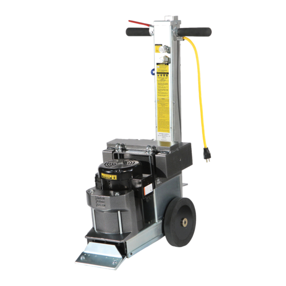
- Page 1 5280 PANTHER WALK-BEHIND SCRAPER ® SERVICE MANUAL Read Manual Before Servicing Machine 402972 Rev J...
-
Page 3: Table Of Contents
Table of Contents Table of Contents ........................................3 Specifications ......................................... 4 Safety ............................................5 General Rules for Safe Operation ................................5 Walk-Behind Scraper Safety Guidelines ............................... 6 Hydraulic Safety......................................7 Electrical Practices ....................................... 8 Troubleshooting Guide ......................................10 Maintenance ...........................................11 Wheel Removal ......................................11 Adding or Changing Hydraulic Fluid ................................11 Inspection of Internal Parts ..................................11... -
Page 4: Specifications
Specifications Product Specifications Vibration Weight Motor Width Length Height Weight* (Machine Only) Power X Axis Y Axis Z Axis 177 lbs 263 lbs 1.0 HP 12.1 14.5 17” (43 cm) 27” (69 cm) 39” (99 cm) (80.3 kg) (119.3 kg) (.75 kW) *Includes removable weights. -
Page 5: Safety
Read the manual carefully to learn equipment applications and limitations, as well as potential hazards associated with this type of equipment. Keep manual near machine at all times. If your manual is lost or damaged, contact National Flooring Equipment (NFE) for a replacement. Personal Maintenance &... -
Page 6: Walk-Behind Scraper Safety Guidelines
Safety Safety WALK-BEHIND SCRAPER SAFETY GUIDELINES Before use, anyone operating this equipment must read and understand these safety instructions. Scraping Beware of hidden obtrusions. Watch out for hidden dangers and protrusions in flooring. Do not use on largely uneven surfaces. Observe location of electrical supplies and extension cords. -
Page 7: Hydraulic Safety
Safety HYDRAULIC SAFETY Maintaining a Safe Work Environment Establishing a safe work environment in and around your hydraulic equipment is extremely important. The easiest and most effective way to avoid problems is to make sure associates understand their equipment, know how to operate the machines safely, and recognize the dangers if handled carelessly. -
Page 8: Electrical Practices
Safety ELECTRICAL PRACTICES WARNING: ELECTRICAL CORDS CAN BE HAZARDOUS. MISUSE CAN RESULT IN FIRE OR DEATH BY ELECTRICAL SHOCK. READ CAREFULLY AND FOLLOW ALL DIRECTIONS. CAUTION: ALWAYS FOLLOW APPLICABLE ELECTRICAL CODES, STANDARDS AND/OR REGULATIONS. CONSULT YOUR LOCAL ELECTRICAL AUTHORITY OR A LICENSED ELECTRICIAN BEFORE ATTEMPTING TO MODIFY AN ELECTRICAL INSTALLATION. ENSURE THAT CIRCUIT AND GROUND FAULT PROTECTION DEVICES AND ALL OTHER ELECTRICAL SAFETY EQUIPMENT ARE FUNCTIONING PROPERLY. - Page 9 Safety ELECTRICAL PRACTICES (CONT’D) How to Use This Table Determine your supply voltage. Determine the total length of your cord including all extension cords. Determine the maximum amp draw for your machine. Trace your voltage across the top of the table to the first length that is greater than or equal to your cord length. Follow the column down to the first row that contains a maximum amp draw greater than or equal to yours.
-
Page 10: Troubleshooting Guide
Troubleshooting Guide Problem Cause Solution No forward movement. Damaged belt. Remove front cover plate and inspect belt. Damaged speed control valve. Inspect speed control valve. Turn counter-clockwise to open valve. Motor shuts off or won’t start. Inspect ON/OFF switch and capacitor. 402972_RevJ... -
Page 11: Maintenance
Maintenance WARNING: ALWAYS UNPLUG MACHINE BEFORE PERFORMING MAINTE- NANCE. WHEEL REMOVAL Examine back of wheels to see if debris is built up. Use a flashlight if needed. Unplug machine; place block under machine between wheels. Securing Screw Use 5/16” hex wrench to remove wheel securing screw (Figure 1). Remove wheel securing cap;... -
Page 12: Control Valve Replacement
Maintenance CONTROL VALVE REPLACEMENT Follow procedure to change fluid in order to drain the tank. Re-place drain plug and filler port cap. Disconnect valve plunger from control linkage. Mark the placement of the four hoses so they can be returned to their original positions. Disconnect and remove the four hoses from valve body. -
Page 13: Parts List And Diagrams
Parts List and Diagrams OVERALL MACHINE 11, 12 5, 13 PART# DESCRIPTION PART# DESCRIPTION 1 400330 WHEEL, DRIVE, LIGHT DUTY, COMPLETE 2 10 72837 CLAMP, CABLE, VINYL COATED, 5/16 2 5280-136 COVER, BLADE 11 6280-161B PLUG, VENT, FILLER CAP 3 5280-137W WRENCH, BLADE 12 6280-161D PLUG, FILLER PORT... -
Page 14: Drive Components
Parts List and Diagrams DRIVE COMPONENTS PART# DESCRIPTION PART# DESCRIPTION 1 5280-1 CHAIN, DRIVE, 40 STRAND 13 5280-129 ECCENTRIC 2 5280-2 SPROCKET, 40BS13 3/4 14 5280-132C PULLEY, PUMP 3 5280-3 SPROCKET, MOTOR, 40BS12X1 15 73903 KEY, 3/16X3/16X2-1/4 4 5280-4 BELT, PUMP DRIVE 16 5280-139 BRACKET, HANDLE ADJUSTMENT 5 74104... -
Page 15: Motor Parts
Parts List and Diagrams MOTOR PARTS PART# DESCRIPTION 1 72353 MOTOR, 1 HP, 116265 2 5280-151 CAPACITOR, MOTOR 3 62182 COVER, CAPACITOR, LEESON 4 401698 BOX, JUNCTION, MOTOR, 3” X 3.3” 5 401869 GASKET, FRAME, JUNCTION BOX, 3X3.33” 6 401699 COVER, JUNCTION BOX, MOTOR, 3”... -
Page 16: Hydraulic Tank
Parts List and Diagrams HYDRAULIC TANK PART# DESCRIPTION 1 5280-120 HOSE, HYDRAULIC, 3/8 X 9.25, 90F/90F 2 5280-162-SV HYDRAULIC TANK BODY, SILVER VEIN 3 6280-214 PLUG, TANK 4 6280-161D HYDRAULIC TANK FILLER CAP 5 6280-162G MAGNET, TANK (NOT SHOWN) 6 70601 STRAINER, TANK MOUNTED 7 72816 FITTING, ELBOW, 90 DEGREE, 3/8”... -
Page 17: Back Of Machine
Parts List and Diagrams BACK OF MACHINE (DOMESTIC SHOWN) PART# DESCRIPTION 1 5280-139C ISOLATOR, HANDLE VIBRATION 2 6280-168 CORD, POWER, SJTOW, 12/3, NEMA 5-15, YELLOW, 27IN 3 72612* ASSEMBLY, CORD, HANDLE, 14/3, NEMA L5-15R, 28” 4 5280-172A LEVER, HANDLE 5 74650 BOLT, HEX FLANGE M10-25 6 73502* STRAIN RELIEF, STRAIGHT 1/2 INCH, .3376-.5686... -
Page 18: Handle
Parts List and Diagrams HANDLE (DOMESTIC SHOWN) PART# DESCRIPTION PART# DESCRIPTION 1 6280-117 FITTING, PUMP 16 5700-76 HOSE, HYDRAULIC, 3/8 X 26, F/F 2 5280-167 HANDLE BODY 17 6280-207 SWITCH, ON-OFF 3 5280-167B COVER, HANDLE BODY 18 6280-215 VALVE BLOCK ASSEMBLY 4 5280-167C PLATE, HANDLE SWITCH 19 73002... -
Page 19: Handle (International Only)
ITEM PART NUMBER DESCRIPTION QTY. NOTES Parts List and Diagrams 404583-028 Assembly, Cord, Handle, 2.5mm/3, NEMA L6-15R, 28in 404313 Cover, Handle, Safety Switch 404172 Assembly, Cord, Power, 1.5mm/3, EU1-16P, 15in HANDLE (INTERNATIONAL ONLY) 404180 Switch, Rocker Breaker, 10A, 220-240V, UVR 403281 Nut, Keps, M4-0.7, Clear Zinc ITEM... -
Page 20: Labels
Parts List and Diagrams LABELS PART# DESCRIPTION 1 403357-XX* KIT, LABELS, 5280, [LANGUAGE] 2 402627 LABEL, PRIVATE, 1.5 X 2 (5280-23XXXX ONLY) 3 402628 LABEL, PRIVATE, 3.5 X 5.5 (5280-23XXXX ONLY) *Suffix (-XX) denotes language: None=English; -FR=French; -NL=Dutch; -DE=German. 402972_RevJ... -
Page 21: Wiring Diagrams
Parts List and Diagrams WIRING DIAGRAM (120V DOMESTIC) 5280 WIRING DIAGRAM PG 1 120V VERSION T-F11 T-F12 2.5mm-BRN 120V T-F21 T-F22 2.5mm-BLU SUPPLY ON/OFF SWITCH 2.5mm-GRN/YEL T-M1 T-F1 GROUND 402972_RevJ... - Page 22 5280 WIRING DIAGRAMS DRAWN BY 2/25/2021 INITIAL RELEASE PROPRIETARY AND CONFIDENTIAL 402972_RevJ THE INFORMATION CONTAINED IN THIS 5280 DIAGRAM DWG. NO. DRAWING IS THE SOLE PROPERTY OF NATIONAL FLOORING EQUIPMENT INC. ANY REPRODUCTION IN PART OR IN SIZE WHOLE WITHOUT THE WRITTEN...
- Page 23 Parts List and Diagrams WIRING DIAGRAM (100V-110V INTERNATIONAL) 5280 WIRING DIAGRAM 100-110V VERSION PG 3 T-F11 T-F12 2.5mm-BRN 100V - 110V T-F21 T-F22 2.5mm-BLU SUPPLY ON/OFF SWITCH 2.5mm-GRN/YEL UNDERVOLTAGE PROTECTED T-R1 T-R2 GROUND GROUND 402972_RevJ...
-
Page 24: Hydraulics
Parts List and Diagrams HYDRAULICS BLEED HYDRAULIC VALVE FWD. PRESS. FLOW TO TOP OF TANK. FWD. PRESS. FLUID FLOW TANK HYDRAULIC MOTOR SUCTION (NEGATIVE PRESS.) POSITIVE HYD. PRESSURE PUMP 402972_RevJ... -
Page 25: Warranty
Warranty National Flooring Equipment Inc. (referred to as “The Company”) warrants that each new unit manufactured by The Company to be free from defects in materials and workmanship in normal use and service for a period of twelve (12) months from date of shipment from The Company to the end user. - Page 28 9250 Xylon Avenue N • Minneapolis, MN 55445 • U.S.A. Toll-free 800-245-0267 • Phone 763-315-5300 • Fax 800-648-7124 • Fax 763-535-8255 Web Site: www.nationalequipmentdirect.com • E-Mail: info@nationalequipment.com...
Need help?
Do you have a question about the PANTHER 5280 and is the answer not in the manual?
Questions and answers