Table of Contents
Advertisement
Quick Links
Advertisement
Table of Contents

Related Manuals for VeriFone UX 410


Summary of Contents for VeriFone UX 410
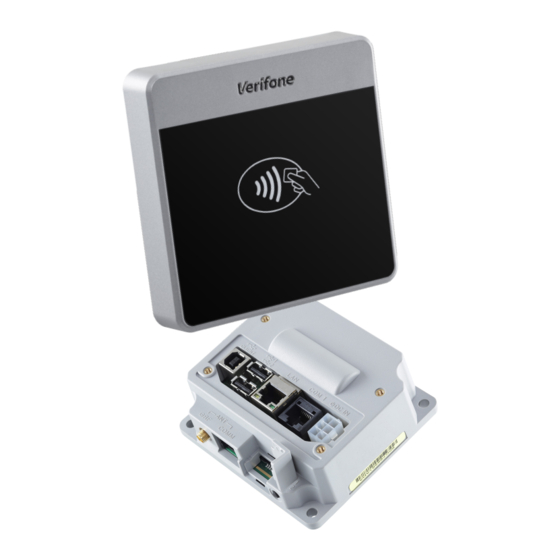
- Page 1 UX 410 Installation Guide Verifone Part Number DOC159-039-EN-B, Revision B...
- Page 2 Verifone, Inc. The information contained in this document is subject to change without notice. Although Verifone has attempted to ensure the accuracy of the contents of this document, this document may include errors or omissions. The examples and sample programs are for illustration only and may not be suited for your purpose.
-
Page 3: Table Of Contents
UX 410 Specifications ........ - Page 4 Caution and UX 410 Caution and Warning Messages ......31 Warning Messages...
-
Page 5: Preface
Port Pinouts. Shows the different pinout specifications for the UX 410. Related To learn more about the UX 410, refer to the following set of documents and their Documentation associated Verifone Part Numbers (VPNs). VPN DOC159-037-EN UX 410 Certifications and Regulations Sheet... -
Page 6: Conventions And Acronyms
Acronym Definitions CTLS Contactless Europay, MasterCard and Visa Integrated Circuit Light-Emitting Diode Merchandise Return Authorization Near Field Communication Radio Frequency RJ45 Registered Jack 45 modular connector Single CI Single Contactless Interface SubMiniature version A connector UX 410 I NSTALLATION UIDE... -
Page 7: Device Overview
HAPTER Device Overview The UX 410 is composed of a Controller Unit and an Antenna Unit. The UX 410 supports transactions in a variety of environments, specifically outdoor and unattended markets. Features and The UX 410 is Verifone's contactless reader device. It creates an economical... -
Page 8: Compliance
ISO 18092 Active Communications (NFC - peer-to-peer mode) • PayPass • payWave • AMEX Expresspay Diversity of Models Verifone provides UX 410 Antenna units for use on the following mounting panels: • Non-metal • Metal UX 410 I NSTALLATION UIDE... -
Page 9: Setup Selecting Unit Location
For safety, do not string cables or cords from your installation cabinet or housing across a walkway. Environmental The front panel of the device is dustproof and fade-proof. The UX 410 is also Factors water-resistant, in accordance with IP65 ratings. -
Page 10: Unpacking The Shipping Carton
Do not use a unit that has been tampered with or otherwise damaged. This unit WARNING comes equipped with tamper-evident labels. If a label or component appears damaged, immediately notify the shipping company and your Verifone representative or service provider. Examining... -
Page 11: Antenna Unit Features
RJ45 PORT SMA PORT MOUNTING POSTS UX 410 Antenna Unit Reverse View Figure 2 The reverse side of the UX 410 Antenna Unit shows the following: • RJ45 host communication connector. • SMA (RF) antenna connector. • Four mounting posts. -
Page 12: Controller Unit Features
SMA/Antenna (RJ45) • SAM Card compartment Finding ARS and There are three switches on the UX 410: two Anti-Removal Switches (ARS) on the Service installation panel side and one Service Switch on the underside of the Controller Switches unit (see... -
Page 13: Removal Protection
Use only if you have the proper authorization and equipment to open system mode. Please contact your Verifone representative for details. Mounting the The UX 410 Antenna Unit is designed to be front mounted to an installation panel, Antenna Unit without further need for any external mounting devices. -
Page 14: Mounting The Controller Unit
For metallic variants (M159-410-1xx-xxx), the installation panel needs to be • metallic, and its size has to be at least 1 cm more. Do not start a contactless transaction before a metallic UX 410 variant is installed correctly on a metallic panel. Mounting the... -
Page 15: Connecting The Antenna Unit To The Controller Unit
NOTE For EMVCo L1 compliance, please use the provided cables. Both connections are necessary for using the UX 410 to operate. Connect one end of the RJ45 plug to the rear of the Antenna and the other To connect units end to the Controller Units. -
Page 16: Installing Or Replacing Sam Cards
(see Figure Observe standard precautions in handling electrostatically sensitive devices. CAUTION Electrostatic discharges can damage the equipment. Verifone recommends using a grounded anti-static wrist strap. Disconnect the device from all power sources. To install or replace SAM cards: Disconnect the device from any external devices. -
Page 17: Connecting Cables
Close the SAM cardholder. Connecting The UX 410 Controller Unit rear panel holds several interface ports for power and Cables communications. Use this section to see how the Controller Unit connects to the Antenna Unit. -
Page 18: Connecting Pin Pads
Accessories and Documentation. Connecting PIN This section shows the attachment of Verifone PIN Pads to the UX 410 Controller Pads Unit to provide users PIN security when conducting their transactions. You can connect the UX 410 Controller Unit with a UX1xx-series PIN Pad device. -
Page 19: Power Connections
The UX 410 connects to external power using a power pack (PWR159-00X-01-A or the CPS12490-4A-R) connected to the power port on the Controller Unit. Connect the power cable to the power port on the UX 410 Controller Unit and the To connect to a power source other end to your power source. -
Page 20: Conducting A Contactless Transaction
2 seconds, prompting you to remove your card. The contactless unit uses various audible and visual confirmations to confirm transactions. NOTE The actual audible and visual confirmations may vary depending on regional and customer requirements. UX 410 I NSTALLATION UIDE... -
Page 21: Specifications
HAPTER Specifications UX 410 This chapter discusses power requirements and other specifications of Specifications the UX 410. Power Consumption • Operation voltage: 12 to 24V DC, 0.5 to 0.7A • Typical Power: 3 W (CTLS reader), 4 W (UX100 display heater), 0.5 W (UX100/110), 3.5 W (RS-232 - PWR Port) - Page 22 PECIFICATIONS UX 410 Specifications Dimensions Antenna Unit • Length: 80 mm (3.15 in) • Width: 80 mm (3.15 in) • Height: 15 mm (0.59 in) Controller Unit • Length: 100 mm (3.94 in) • Width: 90 mm (3.54 in) •...
-
Page 23: Maintenance And Cleaning
These suggestions apply equally to your contactless device, or any of its attachments or accessories. If your device is not working properly, take it to the nearest Verifone-authorized service provider for servicing or replacement. CAUTION Never use thinner, trichloroethylene, or ketone-based solvents - they can deteriorate plastic or rubber parts. - Page 24 AINTENANCE AND LEANING Additional Safety Information THIS PAGE IS INTENTIONALLY LEFT BLANK UX 410 I NSTALLATION UIDE...
-
Page 25: Service And Support
Step 1, to the MRA department at 1-727-953-4172 (U.S.). • Please address the fax clearly to the attention of the “Verifone MRA Dept.” • Include a telephone number where you can be reached and your fax number. UX 410 I... -
Page 26: Accessories And Documentation
You will be issued MRA number(s) and the fax will be returned to you. NOTE One MRA number must be issued for each unit you return to Verifone, even if you are returning several of the same model. Describe the problem(s) and provide the shipping address where the repaired or replacement unit must be returned. -
Page 27: Power Cables
For EMVCo L1 compliance, please use the provided cables. Power Cables Use the following power cables for connecting power to the controller unit. Contact your local Verifone representative or service provider to identify the best cable for your needs. CBL000-039-02-A Australia power cord for PWR159-00X-01-A PSU. - Page 28 ERVICE AND UPPORT Accessories and Documentation THIS PAGE IS INTENTIONALLY LEFT BLANK UX 410 I NSTALLATION UIDE...
-
Page 29: Troubleshooting Guidelines
HAPTER Troubleshooting Guidelines The troubleshooting guidelines provided in the following section are included to assist you to successfully install and configure your UX 410 terminal. If you have problems operating your UX 410 terminal, please read through these troubleshooting examples. - Page 30 ROUBLESHOOTING UIDELINES Peripheral Device Does Not Work THIS PAGE IS INTENTIONALLY LEFT BLANK UX 410 I NSTALLATION UIDE...
-
Page 31: A P P En Di
Si une étiquette ou d'un composant damaged, please notify the semble endommagé, se il vous plaît shipping company and your aviser la compagnie de navigation et Verifone service provider votre fournisseur de services Verifone immediately. immédiatement. Caution Setup page Make sure the installation method Assurez-vous que la méthode... - Page 32 AUTION AND ARNING ESSAGES UX 410 Caution and Warning Messages Table 3 Caution and Warning Messages (continued) Notice Chapter Page English Text French Text Caution Setup page Observe standard precautions in Observer les précautions standard dans handling electrostatically sensitive le traitement de dispositifs sensibles aux devices.
-
Page 33: A P P En Di
PPENDIX Port Pinouts The following tables list the port pinouts for the UX 410. UX 410 Ports Refer to the UX 410 port pinout diagrams. Power Port (DC-in) Connector Function Description +12V to +24V External power from cable Power ground... -
Page 34: 10-Pin Port
INOUTS UX 410 Ports 10-Pin Port Connector Function Description Buzzer Signal +5V DC, 0.1A Power No Connection Power GND No Connection Signal Signal No Connection No Connection Power GND Ethernet Port (LAN) Connector Function Description TXD+ Transmit data + TXD-... - Page 35 Verifone, Inc. 1-800-Verifone www.verifone.com UX 410 Installation Guide Verifone Part Number DOC159-039-EN-B, Revision B...
Need help?
Do you have a question about the UX 410 and is the answer not in the manual?
Questions and answers