Table of Contents
Advertisement
Quick Links
Advertisement
Table of Contents

Subscribe to Our Youtube Channel
Related Manuals for Fisher Scientific accumet AB40


Summary of Contents for Fisher Scientific accumet AB40
-
Page 2: Table Of Contents
TABLE OF CONTENTS 1. INTRODUCTION 2. UNPACKING THE METER 3. GETTING STARTED 3.1. Connectors 4. USING THE METER 4.1. The Electrode 4.2. Display/ Keys 4.3. Screen Display 5. SETUP PROCEDURE CHECK 5.1. Using Setup 5.1.1. Setup Page 1: View last calibration factor 5.1.2. -
Page 3: Introduction
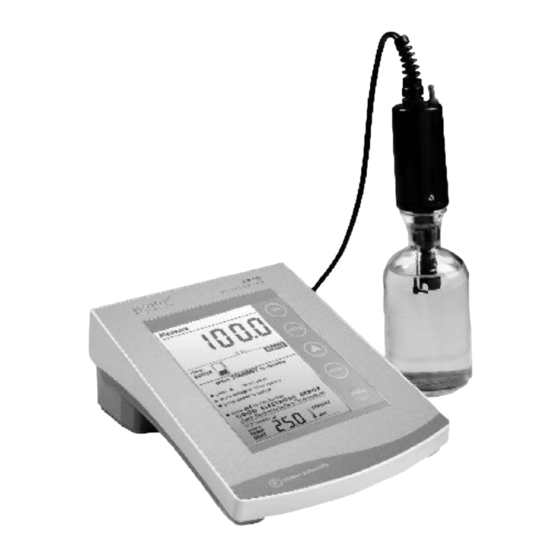
INTRODUCTION Thank you for selecting a Fisher Scientific Accumet Dissolved Oxygen bench-top meter. This instruction manual describes the operation of the meter. The state-of-art meter that you have purchased is easy to operate and will guide you through the various functions by displaying easy to understand prompts. -
Page 4: Unpacking The Meter
UNPACKING THE METER The following is a listing of what you should have received with your new Accumet AB40 Dissolved Oxygen meter: Meter with kit includes: • meter • power supply • BOD probe • membrane kit • Instruction manual Meter only includes: •... -
Page 5: Getting Started
GETTING STARTED 3.1. Connectors 1. Review the layout and arrangement of the rear connector panel. 2. Connect the power adapter’s output power jack to the meter’s rear panel DC input power socket and plug in the adapter to a power source. -
Page 6: Using The Meter
USING THE METER 4.1. The Electrode This meter comes equipped with a self-stirring BOD probe, model 5010, from YSI. Read the accompanying manual prior to installation and operation. The 5010 probe need be plugged into the meter only, as the meter supplies both its operation power and stirring power. 1. -
Page 7: Display/ Keys
4.2. Display/ Keys Overview of the meter screen display and function key layout. Press std key to initiate standardization from measure mode or press std key at the Standardization mode to confirm the standardization and return to measurement mode. % Sat Press to adjust values/ selection. -
Page 8: Screen Display
4.3. Screen Display Familiarize yourself with the layout of the digital screen display. -
Page 9: Setup Procedure Check
SETUP PROCEDURE CHECK 5.1. Using Setup Setup allows you to set the operating parameters of the meter to meet your requirements. There are two ways to access setup, and the parameters that you can set will be different depending on how you accessed setup. - Page 10 The setup button is in essence a scroll key which allows you to change several operating parameters. While in the setup mode you may: Press std to exit from setup to measure screen without making change. Press to set values within each setup option. Press setup to scroll to the next parameter to view or change.
- Page 11 Setup Page 1: View last Setup Page 6 & 7: S T D S olution calibrated Calibration Select number of Factor calibration points for - View the last calibration factor %Sat calibration and 0% offset value. - Select 1 point or 2 point % Sat Note: You will be able to view both Cal calibration for %Saturation.
-
Page 12: Setup Page 1: View Last Calibration Factor
5.1.1. Setup Page 1: View last calibration factor This setup menu allows you to view the last calibration factor in % Sat after standardization is successfully done. To view last calibration factor Access the View Last calibration factor setup page by pressing setup while in measurement mode to view the last calibration factor. - Page 13 If the unit has not been standardized, a series of dashes will appear on the display rather than a number. 3. Press enter to return to measurement mode 4. Press setup to go to the next setup option without making any changes.
-
Page 14: Setup Page 2: Select % Sat Mode
5.1.2. Setup page 2: Select % Sat Mode The setup option allows you to measure DO in % Sat. To select % sat Mode 1. Access the Select % Sat Mode setup page by pressing the setup key while in measurement mode till page displays as figure shown below. -
Page 15: Setup Page 3: Set The Mg/L Mode
5.1.3. Setup Page 3: Set the mg/L mode The setup option allows you to measure DO in mg/L. To select mg/L mode 1. Access the Select mg/L setup page by pressing the setup key while in measurement mode till the page displays as figure shown below. -
Page 16: Setup Page 4: Set The Pressure
5.1.4. Setup Page 4: Set the Pressure The setup option allows you to set the atmospheric pressure (mmHg) value. You are able to set the pressure value in the range of (450mmHg to 825 mmHg). To set Pressure 1. Access the Set the Pressure (mmHg) setup page by pressing the setup key while in measurement mode till the page displays as figure shown below. - Page 17 4. Press enter key to confirm selection and return to measurement mode. 5. Press setup to go to next setup page without making any changes. You can escape setup mode at any time by pressing std. Pressing enter will always return the display to measurement mode after accepting the setup option.
-
Page 18: Setup Page 5: Set The Salinity Value
5.1.5. Setup Page 5: Set the Salinity Value The setup option allows you to set the Salinity (as ppt) value. You are able to set the salinity value in the range of 0.0- 45.0 ppt. To set Salinity 1. Access the Set the salinity (ppt) setup page by pressing the setup while in measurement mode key till the page displays as shown below. -
Page 19: Setup Page 6: Select Number Of User Cal Points For
5.1.6. Setup Page 6: Select Number of User Cal Points for % Sat calibration This setup option allows you to select the number of user calibration points for % Sat calibration to be either 1 or 2. To Select Number of User Cal Points 1. - Page 20 % Sat press setup to select options press enter to accept...
-
Page 21: Setup Page 7: Enable/ Disable Auto Cal
5.1.7. Setup Page 7: Enable/ Disable Auto Cal This setup option allows you to enable the auto calibration for % Sat and mg/L modes. To Enable/ Disable Auto Cal 1. Access the Auto Cal setup page by pressing the setup key while in measurement mode till the page displays as shown in the following page. - Page 22 press setup to select options press enter to accept...
-
Page 23: Setup Page 8: Select The Temperature Unit
5.1.8. Setup Page 8: Select the Temperature Unit This setup option allows you to select unit of measure for Temperature either in °C or °F. To Select Temperature Unit Access the Select Temperature Unit setup page by pressing the setup key while in measurement mode till the page displays as shown below. -
Page 24: Setup Page 9: Enable/ Disable Stability Indicator
5.1.9. Setup Page 9: Enable/ Disable Stability Indicator This setup option allows you to set the stability indicator to be displayed on the screen whenever reading has stabilized, thus minimizes guesswork. To Set Stability Indicator 1. Access the Set Stability Indicator setup page by pressing the setup key while in measurement mode till the page displays as shown below. - Page 25 ST AB L E press setup to select options press enter to accept...
-
Page 26: Setup Page 10: Clear The Calibrated Buffers
5.1.10. Setup Page 10: Clear the Calibrated Buffers This setup option allows you to clear the Calibrated Buffers. To Clear the Calibrated Buffers 1. Access the Clear Calibrated Buffers setup page by pressing the setup key till the page displays as shown below. 2. -
Page 27: User Calibration
USER CALIBRATION 6.1. %Sat- One Point Calibration (Auto) User can do the 100%Sat calibration. The pressure that has been set in the setup will be applied only during the calibration. Accepted window for 100% Sat calibration is 30% - 200%Sat. (Any value that falls within this range will be accepted as 100%Sat) Press std to enter to ‘Standardize’... -
Page 28: Sat - Two Point Calibration (Auto)
6.2. %Sat – Two Point Calibration (Auto) The 0.0%Sat calibration has to be done first if a 2-point %Sat calibration is selected. The 0.0%Sat calibration point will be considered as offset. After successful 0%Sat calibration, meter will prompt for the 100% Sat calibration. -
Page 29: Sat- One Point Calibration (Manual)
6.3. %Sat- One Point Calibration (Manual) User can calibrate to the known value. The accepted window is set to 70% of the default value. Lowest value that can be calibrated is 20.0 %Sat. 1. Press std to enter to ‘Standardize’ screen. Both Upper and lower display shows the present measured value. -
Page 30: Mg/L- One Point Calibration (Auto)
6.4. mg/L- One Point Calibration (Auto) User can do calibration in mg/L. 1. Hold the DO probe in air; wait for the upper display reading to stabilize. 2. Press std to enter to ‘Standardize’ screen. Upper display shows the present measured value while lower display shows theoretical value. -
Page 31: Mg/L One Point Calibration (Manual)
6.5. mg/L One Point Calibration (Manual) User can do calibration in mg/L. 1. Put the DO probe into the known solution to which you want to calibrate the meter. 2. Press std to enter to ‘Standardize’ screen. Both upper and lower display shows the present measured value. -
Page 32: Atc Calibration
6.6. ATC Calibration User can adjust the ATC temperature offset. DO/BOD probe must be connected to be able to access the ATC calibration setup page. To access the temperature calibration mode: 1. Connect DO/BOD probe to back panel of the meter. 2. -
Page 33: Do Theory
Fortunately, the relationship between dissolved salt or salinity and dissolved oxygen is well defined. The Accumet AB40 uses this fact to provide accurate dissolved oxygen measurements in samples whose salinity range from 0 to 40 ppt. -
Page 34: Meter Specifications
METER SPECIFICATIONS Description Accumet AB 40 % Saturation Range 0.0 to 600.0% Resolution Accuracy ±0.5% Full Scale + 1 LSD • Calibration User selectable Auto one (100%) or two point calibration (0% and 100%). • Manual calibration (one point) mg/L Range 0.00 to 60.00 mg/L Resolution... -
Page 35: Cleaning
This meter requires no regular maintenance, but it is recommended to occasionally wipe down the front with a damp cloth from time to time. 10. TROUBLESHOOTING The Accumet AB40 displays pertinent error messages to guide you should an error occur with a measurement or meter operation. Message Description Error Icon Error message for %Sat Cal error. -
Page 36: Setting The Barometric Pressure
11. SETTING THE BAROMETRIC PRESSURE Use the actual local barometric pressure whenever possible. This is obtained from a mercury barometer. Do not use the weather bureau pressure, as it is corrected to sea level. If a barometer is not available, estimate the atmospheric pressure at your altitude from the following table: Altitude in feet mmHg pressure... -
Page 37: Warranty
12. WARRANTY The Fisher Scientific Company (“Fisher”) warrants to the direct purchaser that the accumet AB40 meter and DO probe will be free from defects in material or workmanship for a specified warranty period. During that period, Fisher will repair or replace the product or provide credit, at its sole option, upon prompt notification and compliance with its instructions. -
Page 38: Notice Of Compliance
Warning! To meet or exceed FCC regulations and comply with CE requirements, the Fisher Scientific supplied power supply must be used. Use of a power supply that is not approved by Fisher Scientific may cause safety hazards and/or cause unit to exceed EMC limits and/or damage unit. -
Page 39: Replacement Parts And Accessories
14. REPLACEMENT PARTS AND ACCESSORIES Description Fisher Catalog Number AB40 meter kit includes meter, self- 13-636-AB40 stirring BOD probe (13-620-SSP), membrane kit (13-620-DOM), user manual and power supply. Accumet self-stirring BOD probe 13-620-SSP Adapter allows use of YSI 13-637-DOADPT probes with Accumet meter Dissolved oxygen membrane kit. - Page 40 68X296001 Rev. 1D 01/04...
Need help?
Do you have a question about the accumet AB40 and is the answer not in the manual?
Questions and answers