Nilfisk-Advance MC 6P Service Manual
Hide thumbs
Also See for MC 6P:
- Instructions for use manual (37 pages) ,
- Instructions for use manual (28 pages) ,
- Instructions for use manual (28 pages)
Advertisement
Advertisement
Table of Contents

Related Manuals for Nilfisk-Advance MC 6P


Summary of Contents for Nilfisk-Advance MC 6P
- Page 1 MC 6P SERVICE MANUAL...
- Page 2 Preface This service manual contains detailed description of the main repair work on the cold HPW MC 6P. Repair work requires a suitable testing workplace with the necessary water and power supply. If operating errors are evident, refer the customer to the operating instructions.
-
Page 3: Table Of Contents
Safety instructions Technical data 5 -18 Construction 19 -25 Function 26 -34 Troubleshooting 35-37 38-44 Service / Repair Adjustment / Test 45-47 48-54 Wiring diagrams I. Special tools /Spare parts... -
Page 4: Safety Instructions
Safety instructions For your own safety Observe valid safety regulations for electrical equipment. In particular, observe the following regulations: IEC 60335-2-79 EN 60335-2-79 Additionally: Repair work should be carried Also see national regulations out by persons instructed in electrical installations or by trained electricians only. -
Page 5: Technical Data
Technical data Item number: 107146750 MC 6P-2300/5.0 FA 230/1/60 US Service manual data PUMP: Pressure p pump Pressure p Retaining/opening pressure 16,8 (4,4) Flow Q l/min (gpm) 1 (3) Suction height dry m (ft.) 2,5 (8) Suction height primed m (ft.) - Page 6 Technical data Item number: 107146751 MC 6P-250/1100 FA 400/3/50 EU Service manual data PUMP: Pressure p pump Pressure p Retaining/opening pressure 15,65 Flow Q l/min Suction height dry Suction height primed Pump type Number of pistons Full Ceramic Pump piston type...
- Page 7 Technical data MC 6P-180/1300 FA 400/3/50 EU Item number: 107146752 Service manual data PUMP: Pressure p pump Pressure p Retaining/opening pressure 18,7 Flow Q l/min Suction height dry Suction height primed Pump type Number of pistons Full Ceramic Pump piston type...
- Page 8 Technical data Item number: 107146754 MC 6P-180/1300 FA 220-440/3/60 EXPT Service manual data PUMP: Pressure p pump Pressure p Retaining/opening pressure 18,8 Flow Q l/min Suction height dry Suction height primed Pump type Number of pistons Full Ceramic Pump piston type...
- Page 9 Technical data MC 6P-170/1600 FA 400/3/50 EU Item number: 107146755 Service manual data PUMP: Pressure p pump Pressure p Retaining/opening pressure 23,5 Flow Q l/min Suction height dry Suction height primed Pump type Number of pistons Full Ceramic Pump piston type...
- Page 10 Technical data Item number: 107146758 MC 6P-250/1100 FAXT 400/3/50 EU Service manual data PUMP: Pressure p pump Pressure p Retaining/opening pressure 15,3 Flow Q l/min Suction height dry Suction height primed Pump type Number of pistons Full Ceramic Pump piston type...
- Page 11 Technical data MC 6P-180/1300 FAXT 400/3/50 EU Item number: 107146759 Service manual data PUMP: Pressure p pump Pressure p Retaining/opening pressure 18,7 Flow Q l/min Suction height dry Suction height primed Pump type Number of pistons Full Ceramic Pump piston type...
- Page 12 Technical data Item number: 107146760 MC 6P-180/1300 FAXT 230-400/3/50 NO Service manual data PUMP: Pressure p pump Pressure p Retaining/opening pressure 18,7 Flow Q l/min Suction height dry Suction height primed Pump type Number of pistons Full Ceramic Pump piston type...
- Page 13 Technical data MC 6P-170/1600 FAXT 400/3/50 EU Item number: 107146761 Service manual data PUMP: Pressure p pump Pressure p Retaining/opening pressure Flow Q l/min Suction height dry Suction height primed Pump type Number of pistons Full Ceramic Pump piston type...
- Page 14 Technical data Item number: 107146765 GERNI POSEIDON 6-65 FA 415/3/50 AU Service manual data PUMP: Pressure p pump Pressure p Retaining/opening pressure 18,7 Flow Q l/min Suction height dry Suction height primed Pump type Number of pistons Full Ceramic Pump piston type Cylinder stroke Castrol Alphasyn T 150 Pump oil type...
- Page 15 Technical data Item number: 107146766 MC 6P-250/1100 FA 415/3/50 GERNI Service manual data PUMP: Pressure p pump Pressure p Retaining/opening pressure 15,65 Flow Q l/min Suction height dry Suction height primed Pump type Number of pistons Full Ceramic Pump piston type...
- Page 16 Technical data MC 6P-120/1950 FA 400/3/50 EU Item number: 107146773 Service manual data PUMP: Pressure p pump Pressure p 140 +5 / - 0 Retaining/opening pressure 30,5 Flow Q l/min Suction height dry Suction height primed Pump type Number of pistons...
- Page 17 Technical data Item number: 107146774 MC 6P-120/1950 FAXT 400/3/50 EU Service manual data PUMP: Pressure p pump Pressure p 140 +5 / - 0 Retaining/opening pressure 30,5 Flow Q l/min Suction height dry Suction height primed Pump type Number of pistons...
- Page 18 Technical data MC 6P-120/1950 FA 230-400/3/50 NO Item number: 107146775 Service manual data PUMP: Pressure p pump Pressure p 140 +5 / - 0 Retaining/opening pressure 30,5 Flow Q l/min Suction height dry Suction height primed Pump type Number of pistons...
-
Page 19: Construction
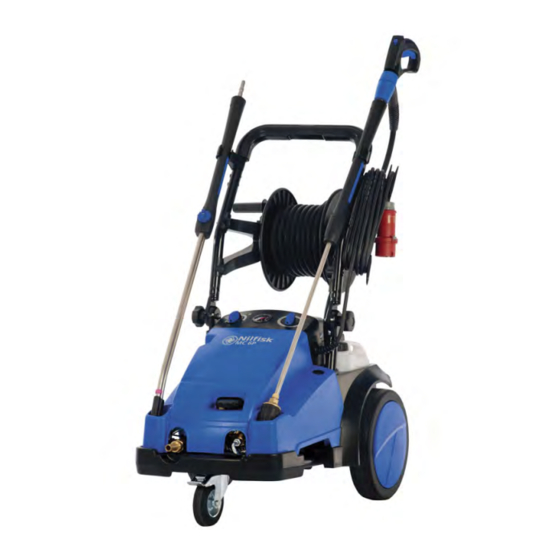
Overview MC 6P Lance holder top Lance Detergent Bottles Pressure gauge Detergent valve ON / OFF switch Cabinet lock Water/pressure regulator View for oil container Lance holder bottom Water inlet + Filter Water outlet MC 6P Cabinet & frame parts SM_MC_6P Ver.2.0_2021... - Page 20 Construction Overview MC 6P ”0” = Stop ”I” = ON ”M” = Manual. Manual means the Auto Start/Stop system is elimina- ted. This is used if the pump is used on suction and not on pressurized water supply. Pressure gauge...
- Page 21 Water/pressure regulator View for oil container Lance holder bottom Water outlet. In this case with hose Water inlet + Filter reel, a HP hose is going from pump outlet to hose reel. MC 6P Cabinet & frame parts SM_MC_6P Ver.2.0_2021...
- Page 22 Water regulator By-pass valve Water outlet Water inlet/Filter The main differences between the three MC 6P 120 bar models and the other models are. The MC 6P 120 bar has…. - No internal detergent system- - No Manometer - Higher water volume - Lower pressure SM_MC_6P Ver.2.0_2021...
- Page 23 Construction MC 6P By-pass valve– FA Models Water regulator By-pass control pistion Flow piston Reed contact Plug for by-pass Unloader housing Injector/non-return valve - Pic. C4: By-pass valve NOT on 120 bar models. SM_MC_6P Ver.2.0_2021...
- Page 24 Construction MC 6P Pump Piston. Special pi- Spring. Special return ston for 120 bar spring for 120 bar Washer for spring Cylinder block models models Oil seals Header ring Inlet valve Secondary seal Thrust collar Back up ring Cylinder head...
- Page 25 Construction MC 6P Motor/Pump Fan cover Lid for oil container End bearing cover Needle bearing Wobble disc Oil container D-bearing cover Cylindrical roller bearing Bearing track Bearing track Oil seal Motor complete Oil plug SM_MC_6P Ver.2.0_2021...
-
Page 26: Function
Function Electrical System, E-box Contactor PCBA Terminal block E-box SM_MC_6P Ver.2.0_2021... - Page 27 Function Operation electrical System Operation of MC 6P FA: The PCB has following functions: 1. To start the motor when starting the machine. 2. To stop the motor when operation of the machine is finished. 3. To run the motor in by-pass for 20 sec. after water flow stop and B4 is ”low” (open).
- Page 28 Function Operation electrical System Datalogger connection SM_MC_6P Ver.2.0_2021...
- Page 29 Function By-Pass valve system MC 6P By-pass valve components for the MC 6P models (not 120 bar models). By-pass valve for MC 6P has internal injector system. SM_MC_6P Ver.2.0_2021...
- Page 30 Function By-Pass valve system_MC 6P 120bar models By-pass valve components for the MC 6P 120 bar models. By-pass valve for MC 6P 120 bar models do not have internal injector system. SM_MC_6P Ver.2.0_2021...
- Page 31 Function By-Pass valve system_MC 6P By-pass valve components are shown in high pressure running mode. The water is flowing from the 4 pump pressure valves through the channel (1) to the injector nozzle (4) and also to the by-pass valve housing area (2 & 3) between the 2 pistons (9) and (10). Pos. (1,2, 3, 4, 5 and 6) is high pressure areas.
- Page 32 Function By-Pass valve system_MC 6P By-pass valve function in high pressure running mode. Motor is running, spray handle is open, water is flowing to the HP nozzle. During operation there is high pressure at pos. 1,2,3,4,5,6. Water flows from the pressure valves (1) through the injector nozzle (4) to the outlet (6) and out to the HP nozzle in the lance.
- Page 33 Function By-Pass valve system_MC 6P By-pass valve function in by-pass mode. Motor is running, spray handle is CLOSED, water is NOT flowing to the HP nozzle. Now the water flow in the bypass valve stop—no flow through the injector nozzle—so no pressure drop.
- Page 34 (PCBA) of the machine. When there is no flow through the flow switch, the flow piston will in this MC 6P design drop down due to gravity and the piston moves away from the reed switch and the reed switch will open and break the circuit.
-
Page 35: Troubleshooting
Troubleshooting General failures Fault Cause Remedy Pressure drop - Air in the system. • Vent the system by operating the spray gun several times at short intervals .If necessarly operate the cleaner for a short time without the High pressure hose - High pressure nozzle connected. - Page 36 Troubleshooting General failures Fault Cause Remedy When the cleaner is switched − The main voltage is too low • Have the electrical or there is a phase failure connections checked. on the motor buzzes without (3 ph model). • Pump needs service starting.
- Page 37 Troubleshooting By-pass valve failures NA6 (NA5) Symptom: Machine doesn’t start when acti- vating the spray gun. Cause: Defective reed switch (3) or stocked flow piston (2). Remedy: Replace defective parts. Symptom: Irregular working pressure. Cause: Injector nozzle (4) is worn. Remedy: Replace injector nozzle.
-
Page 38: Service / Repair
Service / Repair Torque & Tools list Cylinder Head Tool List for NA6 MPU 8 M10 screws for pump assy Unbracho 8 30 Nm Pump Thrust collar Screw driver Description Tool Torque Outlet valves Pull out tool By-pass Valve FA Inlet valves Mandrel and hammer N/A 4 M8 screws for unloa-... - Page 39 Service / Repair Cabinet and oil container Pic. F1: Machine ID Plate Pic. F2: Cabinet Identify the machine version at the The cabinet is disassembled by turning the two • dataplate. lock screws (1) on top of the cabinet. Find the techincal data for the machine Open the cabinet and pull forward.
- Page 40 Service / Repair Pump valves Pic. F7: Valve housing Pic. F8: Thrust collar Disassemble the valve housing from the Be carefull not to damage the surface • • cylinder block by the 8 bolts. inside when disassembling the thrust collar. Be aware of the o-rings and valve parts.
- Page 41 Service / Repair Pump valves Pic. F.11: Header ring Pic. F12: Header ring Assemble header ring in right position. Knob on If the header ring is mounted wrongly and not header ring must be placed in groove in cylin- according to instruction, there is a big risk of derhead.
- Page 42 Service / Repair Pump valves Picture of piston guides Pic. F14: Pressure and suction valves Pic. F15: Pressure and suction valves The pressure valves can easily be taken Lubricate by replacement of valves • • out of the cylinder head. Replace with new parts if necessary.
- Page 43 Service / Repair Oil seals and pistons Pic. F18: Oil seals Pic. F19: Pistons To make replacement easier moisten the Place seals, pistons and springs as • • sleeves with soapy water. shown. Assemble the sleeves using a box • spanner.
- Page 44 Service / Repair D-bearing cover Pic. F22: D-bearing cover Pic. F23: Motor shaft The D-bearing cover is mounted to the Motor shaft with lubrication holes—for • • Motor by four 6mm bolts. better lubrication of the woble disc system. When the bearing is damaged, always •...
-
Page 45: Adjustment / Test
Adjustment / Test Safety valve adjustment Test manometer—1206358. Use adaptor 1220126 for con- necnting the HP hose to the test manometer. Adjustment procedure. The safety valve factory setting for opening pressure is working pressure +25 to +30 bar. Adjustment procedure for safety valve. Connect machine to water supply, and mount test manome- ter with FULL OPEN valve on machine outlet coupling. - Page 46 Adjustment / Test Water regulator adjustment With dismounted blue handle for the water regulator, and machine with- out pressure do the following to ad- just the water regulator: Turn gently the small brass shaft (1) counterclockwise until it JUST touches the surface of the plug (2) Push down the blue handle (3)on the top of the shaft, and position it so the handle stop is positioned on...
- Page 47 Adjustment / Test Cylinder head Tool List for NA6 MPU 8 M10 screws for Unbracho 8 30 Nm Pump Thrust collar Screw driver Description Tool Torque Outlet valves Pull out tool By-pass Valve FA Inlet valves Mandrel and hammer N/A 4 M8 screws for unloa- Primary seals ø24 Seal tool...
-
Page 48: Wiring Diagrams
Wiring diagrams 106420544, 1 ph 230V SM_MC_6P Ver.2.0_2021... - Page 49 Wiring diagrams 106420552 3 ph STAR w.PCBA SM_MC_6P Ver.2.0_2021...
- Page 50 Wiring diagrams 106420554, 3 ph DELTA w.PCBA SM_MC_6P Ver.2.0_2021...
- Page 51 Wiring diagrams 106420556, 3 ph STAR or DELTA w.PCBA SM_MC_6P Ver.2.0_2021...
- Page 52 Wiring diagrams 106420558, 1 ph 230V w.PCBA SM_MC_6P Ver.2.0_2021...
- Page 53 Wiring diagrams 106420559, 1 ph Model SM_MC_6P Ver.2.0_2021...
- Page 54 Wiring diagrams 106420564, 3 ph STAR-DELTA SM_MC_6P Ver.2.0_2021...
-
Page 55: Special Tools /Spare Parts
Special Tools / Spare Parts Part Number Description Remarks Special Tools Adjustment safety valve opening pres- 1206358 Test Pressure Gauge sure 301000383 DATALOGGER Pulling out data from PCBA Additional Materials*** 41455 Grease (-15 C to +130 C) Valve grease 31001229 Pump oil Alphasyn T-150 20 L container 5218433... - Page 56 Notes Notes SM_MC_6P Ver.2.0_2021...
- Page 57 Nilfisk A/S Industrivej 1 9650 Hadsund Denmark www.nilfisk.com...
Need help?
Do you have a question about the MC 6P and is the answer not in the manual?
Questions and answers