Advertisement
Quick Links
Advertisement

Related Manuals for Nilfisk-Advance MC 9P


Summary of Contents for Nilfisk-Advance MC 9P
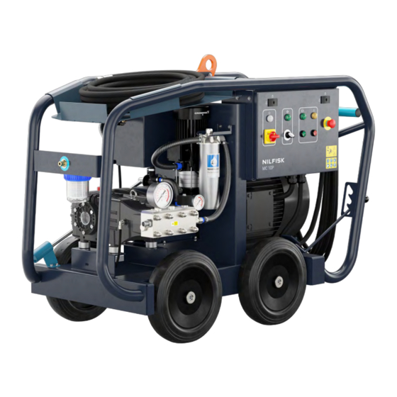
- Page 1 SERVICE MANUAL MC 9P & MC 10P...
- Page 2 Preface This service manual contains detailed description of the main repair work on the MC 9P & MC 10P. Repair work requires a suitable testing workplace with the necessary water and power supply. If operating errors are evident, refer the customer to the operating instructions.
- Page 3 Table of Content p. 4-21 Safety instructions Technical data p. 22-32 p. 33-43 Construction p. 44-47 Function p. 48-49 Troubleshooting p. 50-76 Service / Repair Adjustment / Test p. 77-80 Wiring diagrams p. 81-86 Special tools / Spare parts p. 87 SM_MC 9P_MC 10P Ver.1.0_February_2023...
- Page 4 Safety instructions For your own safety MC9-series, MC10-series Ultra HPW - Mobile - El - CW 400V 3~ 50Hz, 440V 3~ 60Hz, IPX5. 2006/42/EC: EN 1829-1:2021 EN 1829-2:2008 2014/30/EU: EN 61000-3-11:2019 EN 61000-3-12:2011 EN 61000-6-2:2019 Repair work should be carried out by persons instructed in electrical EN 61000-6-4:2019 installations or by trained...
- Page 5 Safety instructions SAFETY INSTRUCTIONS FOR SERVICE TECHNICIANS Before any repair work is started make sure the power supply to the machine is disconnected from/in the wall socket. Repair work must be carried out by instructed technicians in electric installations, or by trained electricians. Check machine safety before start working with the machine: Check that machine is connected to the correct power supply based on the machine ID plate.
- Page 6 Safety instructions ¨ Before starting the VHPW Go to page 22, machine data and look up the VHPW model you are about to use. The info provided there will assist you when reading through this manual. Prior to beginning work, all equipment must be inspected to ensure that it is in safe working condition.
- Page 7 Safety instructions Spraying device: Check daily for visual damage that could impair pressure integrity. Handle and store the spraying device in such a way that it will not get large mechanical shock (e.g. falling onto a concrete floor). MC 10P 800/1100 ONLY: Inspect the dump gun cartridge assembly after each use and lubricate.
- Page 8 Safety instructions Prior to commencing any water blasting work, the area must be barricaded to restrict unauthorized access. Blasting Method: We recommend using a 2 operator* blasting method. The role of the 2nd operator is to attend the pump unit and keep close watch on the 1st operator for fatigue. By using this blasting method the operators can take turns operating the machine.
- Page 9 To reset the machine, turn the button clockwise to release. The VHPW will remain in its neutral state. On MC 9P and MC10P 500 residual pressure can be built up in the hose/ gun. Make sure to release any residual pressure from hose/gun.
- Page 10 Safety instructions MC 9P & MC 10P 500 ONLY: Safety valve: When the VHPW is over pressurized, the safety valve will start to open and excess water is dumped. The safety valve system is factory set and sealed with a tamper-evident sealing. Breaking the seal and performing unau- thorized adjustments to the safety valve system may void the warranty for the VHPW.
- Page 11 Safety instructions MC 9P & MC 10P 500 ONLY: Thermal dump valve: The thermal dump valve protects the pump and LP water line against increased water temperatures when the VHPW is running in bypass mode. When the machine is running in bypass mode and the temperature of the water in the system becomes higher than approx.
- Page 12 Always use the torque values indicated on Page 17 Hose type guide NOTE: The trigger gun for MC 9P 350 & 500 + MC 10P 500 must not be mounted yet. The procedure for venting the wa- ter line and pump from air as described in “Switching on the unit” must be followed prior to mounting the trigger gun.
- Page 13 Safety instructions Connecting two hoses for extension purposes: Always use two wrenches for this procedure. One for tightening nipple/hose fitting and one for holding back on the other nipple/hose fitting. MC 10P 800/1100 ONLY: For pressure above 500 bar—all high pressure hoses must always be secured to each other using connector safety devices.
- Page 14 Hose mounting and Dismounting and follow the torque value listed on Page 17 Hose type guide NOTE: MC 9P 350 has a quick coupling between gun and lance, so here no tools are needed. MC 10P 800 & 1100: Turn on the booster pump selector switch.
- Page 15 Safety instructions After using the unit or before leaving it unattended VHPW machine logout/tagout procedure. This procedure is to be used when work is halted due to breaks etc. It establishes lockout on the VHPW to prevent inju- ry to personnel. All operators shall comply with the procedure.
- Page 16 Safety instructions Machine shut down procedure when work is completed. Press the red stop button and ensure the motor comes to a complete stop. MC 10P 800/1100 ONLY: Turn off the booster pump switch when the motor has come to a full stop. Turn off the main power isolator switch.
- Page 17 Safety instructions High Pressure Hose Fittings & Torque Valid for all models *Info is printed on hose The hose fittings must be tightened with the correct recom- mended torque. NOTE: An open spanner for torque wrench is needed. SM_MC 9P_MC 10P Ver.1.0_February_2023...
- Page 18 Safety instructions SAFETY INSTRUCTIONS FOR MACHINES ABOVE 500 bar Correct mounting of fitting + 2x connector safety Note: If desired by the user or demanded by local devices when mounting an extension hose. laws/regulations, the connector safety device can be exchanged to a hose sleeve protection as shown in above image.
- Page 19 Safety instructions Working positions MC 9P 350-500 MC 9P 500 MC 10P 800/1100 Recoil Force In the above table the recoil force for each machine is listed in Newton (N). Note: The specified recoil force is only valid for the nozzle supplied with the machine at purchase. Info on the supplied nozzle is listed under Nozzle type and Nozzle size.
- Page 20 Safety instructions SAFETY INSTRUCTIONS FOR MACHINES ABOVE 500 bar PPE—Personal Protection Equipment There are several safety precautions for users and service techs that must be fulfilled when working with/on VHP equipment (above 500 bar). A part of that is Personal Protection Equipment—PPE. Below are the PPE Nilfisk recommend to use and sell as accessories.
- Page 21 Safety instructions SAFETY INSTRUCTIONS FOR MACHINES ABOVE 500 bar PPE—Personal Protection Equipment There are several safety precautions for users and service techs that must be fulfilled when working with/on VHP equipment (above 500 bar). A part of that is Personal Protection Equipment—PPE. Below are the PPE Nilfisk recommend to use and sell as accessories.
- Page 22 Technical data SM_MC 9P_MC 10P Ver.1.0_February_2023...
- Page 23 Technical data SM_MC 9P_MC 10P Ver.1.0_February_2023...
- Page 24 Technical data SM_MC 9P_MC 10P Ver.1.0_February_2023...
- Page 25 Technical data SM_MC 9P_MC 10P Ver.1.0_February_2023...
- Page 26 Technical data SM_MC 9P_MC 10P Ver.1.0_February_2023...
- Page 27 Technical data SM_MC 9P_MC 10P Ver.1.0_February_2023...
- Page 28 Technical data SM_MC 9P_MC 10P Ver.1.0_February_2023...
- Page 29 Technical data SM_MC 9P_MC 10P Ver.1.0_February_2023...
- Page 30 Technical data SM_MC 9P_MC 10P Ver.1.0_February_2023...
- Page 31 Technical data SM_MC 9P_MC 10P Ver.1.0_February_2023...
- Page 32 Technical data SM_MC 9P_MC 10P Ver.1.0_February_2023...
- Page 33 Construction — MC 9P 350 Lifting eye Level switch water break tank Compartment for HP hose Safety valve Water inlet connection 10. Water outlet connection Water break tank 11. Manometer Water inlet filter 12. Dump valve E-box 13. Pump Unloader 14.
- Page 34 Construction — MC 9P 350 Handle Power cable Electric motor E-box electric motor Unloader return hose Water line to pump Pump oil level glass Spray handle Spray lance SM_MC 9P_MC 10P Ver.1.0_February_2023...
- Page 35 Construction — MC 9P 500 Lifting eye Level switch water break tank Compartment for HP hose Safety valve Water inlet connection 10. Water outlet connection Water break tank 11. Manometer Water inlet filter 12. Dump valve E-box 13. Pump Unloader 14.
- Page 36 Construction — MC 9P 500 Handle Power cable Electric motor E-box electric motor Unloader return hose Water line to pump Pump oil level glass Spray handle Spray lance SM_MC 9P_MC 10P Ver.1.0_February_2023...
- Page 37 Construction — MC 9P 350/500 A. Main power panel: High pressure pump panel: Main power control light Control light pump Main power switch Start switch—high pressure pump Warning light Stop switch—high pressure pump Emergency stop switch Lock for E-box SM_MC 9P_MC 10P Ver.1.0_February_2023...
- Page 38 Construction — MC 10P 500 Lifting eye Manometer pump Compartment for HP hose Safety valve Water inlet connection 10. Pump Water break tank 11. Parking brake Water inlet filter 12. E-box electric motor E-box 13. Unloader return hose Water outlet connection 14.
- Page 39 Construction — MC 10P 500 Handle Power cable Electric motor Pump oil level glass Spray handle Spray lance Level switch water break tank SM_MC 9P_MC 10P Ver.1.0_February_2023...
- Page 40 Construction — MC 10P 500 Lock for E-box High pressure pump panel: Lock for E-box Control light pump Start switch—high pressure pump A. Main power panel: Warning light Control light Main power 10. Stop switch—high pressure pump Main power switch 11.
- Page 41 Construction — MC 10P 800/1100 Lifting eye Manometer water inlet pump Compartment for HP hose 10. Pump Water inlet connection 11. Secondary water filter Water break tank 12. Booster pump Water inlet filter 13. Parking brake E-box 14. E-box electric motor Water outlet connection 15.
- Page 42 Construction — MC 10P 800/1100 Handle Power cable Electric motor Dump gun Pump oil level glass Spray lance Coupling between motor and pump Level switch water break tank SM_MC 9P_MC 10P Ver.1.0_February_2023...
- Page 43 Construction — MC 10P 800/1100Panel Lock for E-box High pressure pump panel: Lock for E-box Control light pump Start switch—high pressure pump A. Main power panel: Warning light Control light Main power 10. Stop switch—high pressure pump Main power switch 11.
- Page 44 Function Machine schematics; MC 9P 350/500 & MC10P 500 Symbol Description Symbol Desription Booster Pump Rupture Disc Filter—Inlet Safety Valve Filter—Mineral Thermal Dump Valve Float Valve Trigger Gun—Dry Shut Type Level Sensor Trigger Gun—Dump Type Main Pump Unloader Valve Pressure Gauge—Water In- let Pump Pressure Gauge—Outlet...
- Page 45 Function Machine schematics; MC 10P 800/1100 Symbol Description Symbol Desription Booster Pump Rupture Disc Filter—Inlet Safety Valve Filter—Mineral Thermal Dump Valve Float Valve Trigger Gun—Dry Shut Type Level Sensor Trigger Gun—Dump Type Main Pump Unloader Valve Pressure Gauge—Water In- let Pump Pressure Gauge—Outlet Pump SM_MC 9P_MC 10P Ver.1.0_February_2023...
- Page 46 Function Functional Description MC 9P 350/500 & MC10P 500 The booster pump ensures that the main pump (MP) is supplied with sufficient water flow through the MP water Inlet (2-7 Bar). The water inlet filter ensures no dirt/debris/foreign objects etc. from the inlet water source can enter the low pressure water line and damage pump and other components.
- Page 47 Function Functional Description MC 10P 800/1100 The booster pump ensures that the main pump (MP) is supplied with sufficient water flow through the MP water Inlet (2-7 Bar). The water inlet filter ensures no dirt/debris/foreign objects etc. from the inlet water source can enter the low pressure water line and damage pump and other components.
- Page 48 Troubleshooting Resolving “Sticky valves” Symptom: During initial start, water supply and VHPW is turned on but the pump does not deliver water through the high pressure water outlet. The pump does not prime and is running dry. Cause: This can be caused by the inlet valves inside the pump being stuck. (e.g. pump inactivity or prolonged shipment/ storage).
- Page 49 Troubleshooting Symptom Causes and remediations Main switch is turned on; VHPW will not Check power supply connection. run. Make sure the power plug is inserted correctly. Check if automatic fuse is cut-o . If yes turn on fuse again. Motor is humming; Pump providing no Voltage is too low compared to specifi cation.
- Page 50 MC 9P Pump 350 bar Service / Repair Torque—pump SM_MC 9P_MC 10P Ver.1.0_February_2023...
- Page 51 Service / Repair MC 9P Pump 500 bar Disassembling Remove the M10 bolts, and then remove Insert an M6 screw and pull out the the Outlet valve cover. outlet valve cap. Use an O-ring picker tool to remove the O Pull out the valve using a set of pliers.
- Page 52 Service / Repair MC 9P Pump 500 bar Disassembling Front Backside Check the valve (1) for damages, and replace Push the valve out with a brass mandrel. Be if necessary. careful not to scratch the inside of the pump head.
- Page 53 Service / Repair MC 9P Pump 500 bar Disassembling Disassembled view of pump head & manifold SM_MC 9P_MC 10P Ver.1.0_February_2023...
- Page 54 Service / Repair MC 9P Pump 500 bar Pump assembling Lubricate seals and O-rings with waterproof silicone grease. Mount the seals and back ring as shown Assemble White & Black Packing and insert above. Pay attention to the seal sequence...
- Page 55 Service / Repair MC 9P Pump 500 bar Pump assembling Mount the pump head. Push the pump head Mount the Manifold ensure that the cooling until there are no gab (1) between the holes (1) are not blocked before assem- crankshaft housing and pump head.
- Page 56 Service / Repair MC 9P Pump 500 bar Pump assembling Teighten all bolts with the specified torque. Specifications below. Torque specifications Torque specifications SM_MC 9P_MC 10P Ver.1.0_February_2023...
- Page 57 Service / Repair MC 10P Pump 800-1100 bar Check or replacement of pressure and suction valves SM_MC 9P_MC 10P Ver.1.0_February_2023...
- Page 58 Service / Repair MC 10P Pump 800-1100 bar Check or replacement of pressure and suction valves SM_MC 9P_MC 10P Ver.1.0_February_2023...
- Page 59 Service / Repair MC 10P Pump 800-1100 bar Check or replacement of water seals SM_MC 9P_MC 10P Ver.1.0_February_2023...
- Page 60 Service / Repair MC 10P Pump 800-1100 bar Check or replacement of water seals SM_MC 9P_MC 10P Ver.1.0_February_2023...
- Page 61 Service / Repair MC 10P Pump 800-1100 bar Check or replacement of water seals Torque specification BLIND NUTS PUMP HEAD The blind locking nuts on the pump head must be tightened in the following order: 1-2-3-4-1-5-6-7-8-5 First pre-tighten with 70 Nm SM_MC 9P_MC 10P Ver.1.0_February_2023...
- Page 62 Service / Repair MC 10P 800-1100 Motor assembly Coupling - Motor side Push the taper bushing onto the motor shaft. Ensure the taper bushing key slot is aligned with the motor shaft key slot. Depth of the taper bushing is enough for the coupling housing and shaft face to be levelled. Attach the coupling housing into the taper bushing.
- Page 63 Service / Repair MC 10P 800-1100 Motor assembly Align MPU / mount pump Lift the pump onto the frame, MC10-500 direct onto the frame MC-800/MC-1100 spacer between frame Mount flat washer, spring washer on bolt (x4) and loosely tighten so pump still can be aligned/adjusted. Shim pump where necessary.
- Page 64 Service / Repair MC 10P 800-1100 Motor assembly Align MPU / mount pump SM_MC 9P_MC 10P Ver.1.0_February_2023...
- Page 65 Service / Repair MC 10P Dump gun maintenance Cartridge assembly spare parts In below table it is indicated which machines have a dump gun. Also the Nilfisk cartridge assembly spare part numbers are provided. VHPW item VHPW name Trigger gun Dump gun max.
- Page 66 Service / Repair MC 10P Dump gun maintenance Using only your fingers, snap the cartridge assembly After re-assembly of the cartridge – the trigger must sideways out of the retaining groove at the lower end be dismounted for lubrication. of the cartridge nut. Lubricate o-rings and seals. Use a mandrel to punch out the pins from the side To assemble simply reverse the proces.
- Page 67 Service / Repair Nozzle Type Guide SM_MC 9P_MC 10P Ver.1.0_February_2023...
- Page 68 Service / Repair MC 10P Rupture disc In the table below is specified which rupture disc kit should be used when a rupture disc has been triggered and needs to be replaced. A rupture disc kit consists of a rupture disc, spring, ball, a name plate, and a wire for fixing the name plate to the rupture disc housing.
- Page 69 Service / Repair Burst Disc MC 10 800/1100 Burst disc on 800 bar MC 10 Burst disc on 1100 bar MC 10 Screw and washer for top cover. Top cover Top fitting Washer, support Burst disc Seat f. burst disc Spring Spring guide Ball, stainless steel...
- Page 70 Service / Repair MC 9P Unloader Valve 350 Bar Every 500 working hours (approximately 12500 cycles of the system), check and lubricate the seals with water re- sistant grease. Every 1000 working hours (approximately 25000 cycles of the system), check for wear of the seals and internal parts and, if necessary, replace with original parts.
- Page 71 Service / Repair MC 9P Safety Valve 350 Bar Every 400 working hours (approximately 10000 cycles of the system), check and lubri- cate the seals with water resistant grease. Every 800 working hours (approximately 20000 working cycles of the system), control the wear of the seals and internal parts and, if necessary, replace with original parts.
- Page 72 Service / Repair MC 9P—10P Unloader Valve 500 Bar Every 500 working hours (approximately 12500 cycles of the system), check and lubricate the seals with water re- sistant grease. Every 1000 working hours (approximately 25000 cycles of the system), check for wear of the seals and internal parts and, if necessary, replace with original parts.
- Page 73 Service / Repair MC 9P—10P Safety Valve 500 Bar Every 500 working hours (approximately 12500 cycles of the system), check and lubricate the seals with water resistant grease. Every 1000 working hours (approximately 25000 cycles of the system), check for wear of the seals and internal parts and, if necessary, replace with original parts.
- Page 74 Service / Repair Maintenance by operator Regular Service. Period as indicated Each use 1st 50 hrs Every 500 hrs When needed Check pump oil level ⚫ Change pump oil Recommended oil: See “Specifications” ⚫ ⚫ Usage: See “Specifications” Check water inlet filter. Clean or replace cartridge if needed ⚫...
- Page 75 Ordinary Maintenance The following maintenance must be carried out for each 500 (*400) hours of VHPW operation. This maintenance must be performed by a trained service technician only. MC 9P 350 MC 9P 500 MC 10P 500 MC 10P 800...
- Page 76 Service / Repair Maintenance by service technician Oil type alternatives: Use OIL type SAE 15W-40 or equivalent. Here are some recommended types of oil: BRAND TYPE AGIP: F.1 Super motor oil 15W-40 Vanellus C 15W-40 CASTROL: GTX 15W-40 ESSO: Uniflo 15W-40 MOBIL: Super M 15W-40 SHELL:...
- Page 77 Unloader adjustment 350 bar Adjustment / Test Always use the test manometer when adjusting unloaders and safety valves. Adjustment method MC9-350: Part 1 adjustment: Set maximum adjustment pressure for the unloader to 350-360bar STEP 1 – Remove nut (1), handle (2), washer (3) and spring (4) STEP 2 –...
- Page 78 Unloader adjustment 350 bar Adjustment / Test Re-assemble the unloader. Install spring, washer, handle and the counter nut Tighten then 8mm nut (1) so top of nut is level with end of threads. Install the black cap (3) on top of the handle Turn the handle (2) clockwise all the way to its stop by hand.
- Page 79 Safety valve adjustment 350 bar Adjustment / Test SAFETY VALVE ADJUSTMENT STEP 1. Tighten unloader and safety valve till reach 350bar without water drops coming from safety valve. The pressure is worked up to 350bar by alternately tightening unloader valve and safety valve. Check that the maximum pressure adjustment of unloader is in range 350-360bar(part 1 adjustment page 69).
- Page 80 Unloader/safety adjustment 500 bar Adjustment / Test Unloader valve Safety valve STEP 1. Tighten unloader and safety valve till reach 500bar without water dripping from safety valve bottom. The pressure is worked up to 500bar by alternately tightening unloader valve and safety valve. STEP 2.
- Page 81 Wiring diagrams MC 9P 106420600_P1 SM_MC 9P_MC 10P Ver.1.0_February_2023...
- Page 82 Wiring diagrams MC 9P 106420600_P2 SM_MC 9P_MC 10P Ver.1.0_February_2023...
- Page 83 Wiring diagrams MC 10P 106420605_P1 SM_MC 9P_MC 10P Ver.1.0_February_2023...
- Page 84 Wiring diagrams MC 10P 106420605_P2 SM_MC 9P_MC 10P Ver.1.0_February_2023...
- Page 85 Wiring diagrams MC 10P_w_BoosterPump 106420606_P1 SM_MC 9P_MC 10P Ver.1.0_February_2023...
- Page 86 Wiring diagrams MC 10P_w_BoosterPump 106420606_P2 SM_MC 9P_MC 10P Ver.1.0_February_2023...
- Page 87 Special tools / Spare parts Part Number Description Remarks 101221057 Service tool MC9 CK/NIL-K Pump tools for MC 9P 350 bar Service tool MC9-10 NIL-H/CH & NIL- 101221058 Pump tools for MC 9P—10P 500 bar A/Penta 101221059 Service tool MC10 NIL-Y/VY...
Need help?
Do you have a question about the MC 9P and is the answer not in the manual?
Questions and answers