
Related Manuals for Moxa Technologies EDS-G205-1GTXSFP


Summary of Contents for Moxa Technologies EDS-G205-1GTXSFP
-
Page 1: Hardware Installation Guide
EDS-G205-1GTXSFP Hardware Installation Guide Moxa EtherDevice Switch First Edition, April 2015 2015 Moxa Inc. All rights reserved. P/N: 1802002051030... -
Page 2: Package Checklist
Overview The EDS-G205-1GTXSFP switches are equipped with 5 Gigabit Ethernet ports (4 10/100/1000BaseT(X) ports and 1 combo 10/100/1000BaseT(X) or 100/1000BaseSFP port), making them ideal, economical solutions for demanding, high bandwidth Gigabit Ethernet applications. In addition, the built-in relay warning function alerts system administrators when... -
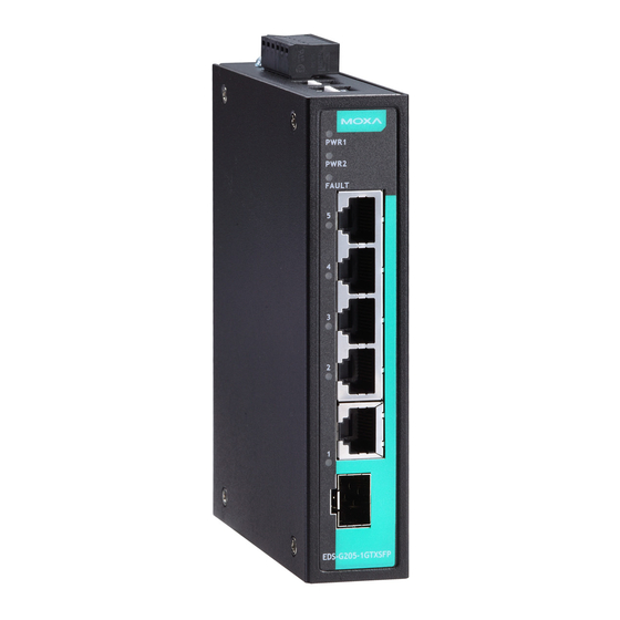
Page 3: Panel Layout Of The Eds-G205-1Gtxsfp
Panel Layout of the EDS-G205-1GTXSFP 1. Terminal block for power input (PWR1, PWR2) and relay output 2. PWR1: LED for power input 1 3. PWR2: LED for power input 2 4. FAULT: LED indicator 5. 10/100/1000BaseT(X) LED indicator (Amber: 10/100M;... -
Page 4: Mounting Dimensions, Unit = Mm (Inch)
Mounting Dimensions, unit = mm (inch) - 4 -... -
Page 5: Din Rail Mounting
DIN Rail Mounting The aluminum DIN rail attachment plate should already be fixed to the back panel of the switch when you take it out of the box. If you need to reattach the DIN rail attachment plate, make sure the stiff metal spring is situated towards the top, as shown in the figures below. -
Page 6: Wiring Requirements
STEP 3: Once the screws are fixed in the wall, insert the four screw heads through the large parts of the keyhole-shaped apertures, and then slide the switch downwards, as indicated. Tighten the four screws for added stability. Wiring Requirements WARNING Safety First! Turn the power off before disconnecting modules or wires. -
Page 7: Grounding Your Moxa Switch
• We strongly advise labeling the wiring for all devices in the system. Grounding Your Moxa Switch Grounding and wire routing help limit the effects of noise due to electromagnetic interference (EMI). Run the ground connection from the ground screw to the grounding surface prior to connecting devices. ATTENTION This product is intended to be mounted to a well-grounded mounting surface, such as a metal panel. -
Page 8: Communication Connections
ATTENTION Before connecting the switch to the DC power inputs, make sure the DC power source voltage is stable. Communication Connections EDS-G205-1GTXSFP switches have 2 types of communication port: • 4 10/100/1000BaseT(X) Ethernet ports • 1 combination 10/100/1000T(X) or 100/1000BaseSFP port 10/100/1000BaseT(X) Ethernet Port Connection The 10/100/1000BaseT(X) ports located on switch’s front panel are used... - Page 9 RJ45 (8-pin) to RJ45 (8-pin) Cross-Over Cable Wiring 100/1000BaseSFP (mini-GBIC) Fiber Port One of the Gigabit Ethernet ports on the EDS-G205-1GTXSFP is an SFP slot, which requires 100M or 1G mini-GBIC fiber transceivers to work properly. Moxa provides complete transceiver models for various distance requirements.
-
Page 10: Redundant Power Inputs
Alarm Contact The EDS-G205-1GTXSFP has one alarm contact located on the top panel. For detailed instructions on how to connect the alarm contact power wires to the two middle contacts of the 6-contact terminal block connector, see the Wiring the Alarm Contact section on page 7. -
Page 11: Led Indicators
To actively update DIP switch settings, power off and then power on the switch. LED Indicators The front panel of the EDS-G205-1GTXSFP switch contains several LED indicators. The function of each LED is described in the table below. Color State... -
Page 12: Auto Mdi/Mdi-X Connection
Auto MDI/MDI-X Connection The Auto MDI/MDI-X function allows users to connect the switch’s 10/100/1000BaseT(X) ports to any kind of Ethernet device, without paying attention to the type of Ethernet cable being used for the connection. This means that you can use either a straight-through cable or cross-over cable to connect the switch to Ethernet devices. -
Page 13: Environmental Limits
Alarm Contact One relay output with current carrying capacity of 1A @ 24 VDC Power Requirements Input Voltage 12/24/48 VDC (9.6 to 60 VDC), redundant input Input Current @ 24VDC 0.16 A Connection One removable 6-pin terminal block Overload Current Present Protection Reverse Polarity...
Need help?
Do you have a question about the EDS-G205-1GTXSFP and is the answer not in the manual?
Questions and answers