Table of Contents
Advertisement
Quick Links
Advertisement
Table of Contents

Related Manuals for Microtronics BLUEFORCE SMART PRO


Summary of Contents for Microtronics BLUEFORCE SMART PRO
- Page 1 Professional Instruments Instructions for use...
-
Page 2: Table Of Contents
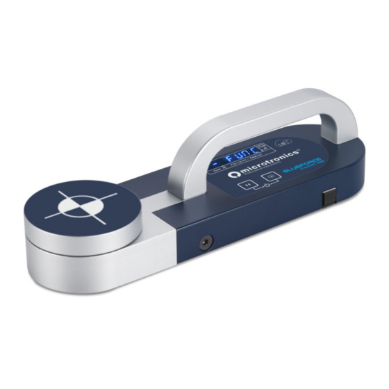
THANK YOU! For choosing a Microtronics product BlueForce Smart Pro is an instrument for the measurement of crushing forces on automatic doors and motorised gates. It is compulsory to observe the following rules of use and maintenance Use is reserved to qualified personnel only... -
Page 3: Blueforce Smart Pro Features
BlueForce Smart Pro features BlueForce Smart Pro is equipped with a lithium-ion battery that can be recharged via USB using the cable supplied. See page 23 for more information on charging. Saved measurements can be transferred to the Blueforce software, previously installed on the computer, using the supplied USB cable. -
Page 4: Instrument Functions - Turn On
Instrument Functions - Turn on Buttons Functions Different functions are associated with the buttons depending on the duration of pressure: Short pressure <0.5 seconds Long pressure >2.0 seconds ON/OFF: Right button + Left button pressed simultaneously for more than 3 seconds, turn the instrument ON or OFF. -
Page 5: Test Measurement - Blueforce Cloud Area
EC declaration of conformity, the maintenance log and the acceptance and testing reports. The use of the BlueForce Cloud area requires the creation of your own account. www.microtronics.it/start.html Link for registration: QR-Code). - Page 6 Detailed Instrument Functions Reading Measurement Parameters with the Instrument After turning on, press the left button briefly to go to the memory location of one of the measurements made, e.g., No. 1. Then, by briefly pressing the right button, you can scroll through the parameters and other functions (see list below). Fd : Maximum amplitude of force peak (N) Td : Force peak duration (s) Fs : Average value of the static force (N)
-
Page 7: Detailed Instrument Functions
Detailed Instrument Functions Reading of measurements carried out and FUNC Menu To access the FUNC menu, scroll through the saved force measurements by briefly pressing the left button, after the last measurement the FUNC menu is displayed, briefly press the right button to access the menu. In the example below, 5 memory locations are shown: locations 1, 2, 4 contain the measurement parameters, while the locations with dashes indicate measurements without parameters (deleted). - Page 8 Detailed Instrument Functions CAL: This function indicates the date of the last calibration (format DD/MM/YY); long press the right button to display. The bAtt function indicates the battery charge status (from 10% to 90%). N.B. for recharging see page 23. NEt function indicates the reception status of the GSM/GPS system.
-
Page 9: Displaying Measurements In Mobile Devices
Displaying Measurements in Mobile Devices Test Measurement and Visualisation on Smartphone 1) Use your smartphone to access the Cloud area with the log-in information obtained after user registration (see page 5). 2) Check that the serial number of your instrument is set correctly in the BlueForce Info menu. 3) Turn on the instrument and make a Test Measurement (see page 5). - Page 10 Displaying Measurements in Mobile Devices 2) Below, if you have chosen to create a new door, you will be prompted to enter the Name and Type of door (see example on the left). If, on the other hand, you have chosen to use an existing door, you must click on the Type of door, then click on the detail box and then select the Measurement point (see example on the right).
-
Page 11: Processing Of Measurements Saved In The Cloud Area
Processing of Measurements saved in the Cloud area Association after execution of measurements This procedure allows you to associate the measurements saved in the Cloud area to a Door/Customer, at a later time after execution. (The following graphical representation shows the use with a PC, however, the operation can also be done with mobile devices). - Page 12 Processing of Measurements saved in the Cloud area 5) Then select one of the points available in the Measurement Point drop-down menu (the detailed Description provided for by the Standard is available under the menu), then proceed to select the test, e.g. no. 1. N.B.
-
Page 13: Use Of The Ftp Thermal Printer
Use of the FTP Thermal Printer Printing Measured Parameters with the FTP Thermal Printer Turn on the printer by pressing and holding the power button for at least 2 seconds (the power indicator lights up). The printing of the measurement parameters is done for every single saved measurement using the Print function available after reading the parameters, e.g.: Fd ->... - Page 14 Installation - BlueForce Software for Windows PC Software for Windows PC - Download Web link to download BlueForce software for PC- Windows: www.microtronics.it/start.html To download updates, visit: www.microtronics.it/area_download.html ATTENTION ! The file is not harmful, please allow your Browser or Antivirus to download the file Setup_blu_en.zip or the update_blueforce_en.zip...
-
Page 15: Blueforce Software Launch - Serial Port Setup
BlueForce Software launch - Serial Port Setup Software Launch - Warnings When starting the BlueForce software for the first time, some warnings may be displayed: Calibration date setting: he software will prompt you to download at least one test from the instrument to enable the calibration date (this can be done after setting up the serial port). -
Page 16: Blueforce Software - Main Functions
BlueForce Software - Main functions BlueForce Software - Overview (1) Measurements list area - Measurements transferred from the instrument with the USB cable are listed in the left area (2) Measurements management area - The central area allows the association of measurements from the list to the doors (3) Detail area - On the right side you can view the details of the doors added. - Page 17 BlueForce Software - Main functions Before associating the measurements in the left box, it is necessary to create at least one Verifier, then a Customer and finally a Door (N.B. a new door must contain at least one description in the Door Identification field). The main menu at the top of the screen can be used for these operations, or simply right-click on the Verifier and use the contextual window to Add, Edit, Delete, etc.
-
Page 18: Blueforce Software - Additional Functions
Door: in this menu you can edit the door data and start the print preview. Tests: in this menu it is possible to modify only some data of the selected measurement To download BlueForce software updates visit: www.microtronics.it/area_download.html - 18 -... - Page 19 BlueForce Software - Additional functions Print Report The Print Report consists of several pages, the contents of which include installer, customer and door data. The data can be edited before printing in the Door Detail menu. Print Preview The Print Preview allows you to view and add more details about the report before printing it;...
-
Page 20: Using The Instrument - Measurement Positions
Using the Instrument - Measurement Positions Accessories Assembly To install the accessories (Straight, Angular and Vertical) it is necessary to remove the handle of the instrument using the supplied hexagonal key (1). The support (supplied with the straight accessory) can then be fitted and secured to the handle with the large knob screw supplied (2). - Page 21 Using the Instrument - Measurement Positions Correct use of the instrument WARNING! Follow the rules of "good use and safety at work". Measurement Positions (1) Sliding door, instrument with straight accessory+element (50 cm total) (2) Hinged door, instrument with straight accessory+element (50 cm total) (3) Vertical door with straight accessory+element (50 cm total) (4) Vertical door with angular accessory (2.5 m total) (5) Vertical door with vertical accessory+element (50 cm total)
-
Page 22: En12453 Informative Appendix
EN12453 Informative Appendix Appendice Informativa EN12453 For further information, please visit www.microtronics.it under "Measurements and Compliance" or "Training Courses". TRAINING COURSES PROGRAM Briefly, what does EN 12453 describe? The EN 12453 Standard " Industrial, commercial and garage doors and gates - Requirements and test methods - Safety in use"... -
Page 23: Battery Recharging And Instrument Maintenance
The hardware of the products is guaranteed for 24 months from the date of delivery of the product, during which time any part found to be defective will be replaced or repaired free of charge. Products in need of repair must be returned to Microtronics or to a Microtronics authorised service company only after approval. -
Page 24: Technical Data - Ec Declaration
Technical Data - EC Declaration Technical Data Dimensions and weight: 280x80x50mm - approx. 1.6Kg Power supply: non-removable Li-ion battery 650mAh – rechargeable via USB 5Vdc 500mA Local storage capacity: 80 tests Force acquisition interval: 6 sec, sampling 1kHz Force measurement range: 0-2000N (mechanical stop at approx. 2100N) Force measurement resolution: 1N Dynamic time measurement resolution: 0.01s Maximum force measurement error: range from 25 to 400N: ±0.5% F.S.;... -
Page 25: General Provisions
Microtronics will NOT be liable for lost profits, direct or indirect incidental or consequential damages, or any other damages of economic nature, even if Microtronics or any reseller knew of the possibility of such damages. The law of some countries does not allow the exclusion or limitation of liability for incidental or consequential damages, so the above limitation or exclusion may not apply to you. - Page 26 ...designed and developed around the needs of installers... Microtronics S.r.l. Via Schiavonia n° 93 Casale sul Sile 31032 (TV) Italy Tel. 0422-827178 - www.microtronics.it - blueforce@microtronics.it All Microtronics design and manufacturing takes place in Italy...
Need help?
Do you have a question about the BLUEFORCE SMART PRO and is the answer not in the manual?
Questions and answers