
Related Manuals for Microtronics myDatalogEASY IoTmini


Summary of Contents for Microtronics myDatalogEASY IoTmini
- Page 1 User manual myDatalogEASY IoTmini Cover Valid from: Firmware version: 01v015 Server version: 47.10 Hardware version: 1.0 301115 | Rev.01...
- Page 3 Chapter 1 Table of contents Chapter 1 Table of contents Cover Chapter 1 Table of contents Chapter 2 Declaration of conformity Chapter 3 Specifications Chapter 4 General specifications 4.1 Translation 4.2 Copyright 4.3 General descriptive names 4.4 Safety instructions 4.4.1 Use of the hazard warnings 4.4.2 General safety instructions 4.4.3 Safety and preventative measures for handling wireless modules 4.4.3.1 Safety and precautionary measures for the wireless module installation...
- Page 4 5.5 Registration memory blocks 5.5.1 REG_SYS_FLASH 5.5.2 REG_APP_OTP Chapter 6 Storage, delivery and transport 6.1 Inspection of incoming deliveries 6.2 Scope of supply 6.3 Storage 6.4 Transport 6.4.1 Transporting power supply units 6.5 Return Chapter 7 Installation 7.1 Dimensions 7.2 Assembling the myDatalogEASY IoTmini 7.3 Installing the myDatalogEASY IoTmini 7.3.1 Wall mounting 7.3.2 Top-hat rail assembly...
- Page 5 Chapter 1 Table of contents 7.5.8.1 Switchable sensor supply VOUT 7.5.8.2 Switchable sensor supply VEXT 7.5.8.3 Switchable sensor supply VEXTRS232 7.5.8.4 Isolated switch contact (NO, CC) 7.5.9 Technical details about energy management 7.5.10 Technical details about the energy supply 7.5.10.1 PSU413D+ AP (300524) 7.5.10.2 PSU413D AP (300525) 7.5.10.3 PSU713 BP (300526) 7.5.10.4 PSU DC (300529)
- Page 6 9.2.2 Device configuration 9.2.2.1 Comments 9.2.2.2 Measurement instrument Chapter 10 rapidM2M Studio 10.1 General 10.2 Prerequisites Chapter 11 myDatanet server 11.1 Recommended procedure 11.1.1 Creating the site Chapter 12 Device Logic (Pawn) 12.1 General 12.1.1 Direct entry of a device logic 12.1.2 Uploading a binary file 12.1.3 Using the CODEbed of the web-based development environment rapidM2M Studio 12.2 Compiler options...
- Page 7 Chapter 1 Table of contents 12.3.6.1 Constants 12.3.6.2 Callback functions 12.3.6.3 Functions 12.3.7 LoRa 12.3.7.1 Constants 12.3.7.2 Callback functions 12.3.7.3 Functions 12.3.8 Registry 12.3.8.1 Constants 12.3.8.2 Callback functions 12.3.8.3 Functions 12.3.9 Position 12.3.9.1 Arrays with symbolic indices 12.3.9.2 Constants 12.3.9.3 Functions 12.3.10 Math 12.3.11 Char &...
- Page 8 12.3.17.2 Functions 12.3.18 Solenoid switch 12.3.18.1 Constants 12.3.18.2 Callback Funktionen 12.3.18.3 Functions 12.3.19 Power management 12.3.19.1 Arrays with symbolic indices 12.3.19.2 Constants 12.3.19.3 Callback functions 12.3.19.4 Functions 12.4 Device Logic error codes 12.5 Syntax 12.5.1 General syntax 12.5.1.1 Format 12.5.1.2 Optional semicolons 12.5.1.3 Comments 12.5.1.4 Identifier 12.5.1.5 Reserved keywords...
- Page 9 Chapter 1 Table of contents 12.5.4.4 Multi-dimensional arrays 12.5.4.5 Arrays and the "sizeof" operator 12.5.5 Operators and expressions 12.5.5.1 Notational conventions 12.5.5.2 Expressions 12.5.5.3 Arithmetic 12.5.5.4 Bit manipulation 12.5.5.5 Assignment 12.5.5.6 Comparative operators 12.5.5.7 Boolean 12.5.5.8 Other 12.5.5.9 Priority of the operators 12.5.6 Statements 12.5.6.1 Statement label 12.5.6.2 Composite statements...
- Page 10 Chapter 13 Data Descriptor Chapter 14 API 14.1 Frontend API 14.2 rapidM2M Playground 14.2.1 Overview Chapter 15 Maintenance 15.1 General maintenance 15.2 Replacing the power supply unit 15.2.1 Charging the power supply unit 15.3 Power supply units with integrated energy store Chapter 16 Removal/disposal Chapter 17 Troubleshooting and repair 17.1 General problems...
-
Page 11: Chapter 2 Declaration Of Conformity
Chapter 2 Declaration of conformity Chapter 2 Declaration of conformity Rev. 01... -
Page 13: Chapter 3 Specifications
Chapter 3 Specifications Chapter 3 Specifications Voltage Rechargeable battery: supply PSU413D+ AP : 13,6Ah, Li-Ion , integrated overvoltage protection PSU413D AP : 13,2Ah, Li-Ion , integrated overvoltage protection Battery: PSU713 BP : 13Ah Direct power supply: PSU DC : DC protective circuit PSU DC+ : 900mAh, Li-Po , DC protective circuit PSU AC : 900mAh, Li-Po , 230VAC power supply unit Additional information is provided in "Technical details about the energy supply"... - Page 14 Universal 4 x analogue or digital inputs Modes: 0/4...20mA: Resolution 6,3µA, max. 23,96mA, load 96Ω 0...2V: Resolution 610µV, max. 2,5V, load 10k086 0...10V: Resolution 7,97mV, max. 32V, load 4k7 PWM: 1...99%, max. 100Hz, min. pulse length 1ms, load 10k086 Frequency: 1...1000Hz, 10k086 Digital: max.
- Page 15 Chapter 3 Specifications Outputs 2 x switchable 3,3V supply (max. 180mA ) 1 x switchable and adjustable sensor supply The device logic can be used to vary the output voltages in the range of 5...24V . 5V : 4,75V at I = 50mA nominal : 11,7V at I...
- Page 16 Memory for 256kB (uncompressed size) the PAWN binary Additional information is provided in "Memory organisation" on page 31. Data Bluetooth Low Energy: transmission Range: 20m (depending on the environmental conditions) LoRa: Supported frequencies:868MHz, 915MHz The universal inputs 3 and 4 are only available if the RS485 interface is not used. In order for the external temperature sensor to be used, the chargeable feature "Activation code temperature input(300542)"...
-
Page 17: Chapter 4 General Specifications
Chapter 4 General specifications Chapter 4 General specifications The information in this manual has been compiled with great care and to the best of our knowledge. The manufacturer, however, assumes no liability for any incorrect specifications that may be provided in this manual. -
Page 18: Use Of The Hazard Warnings
Important note: The manufacturer's products that are designed for outdoor use include extensive protection against moisture and dust penetration. If these products are connected to the power supply or sensors by cables with connectors rather than permanently installed cables, the susceptibility of the connector and socket to moisture and dust penetration is significantly higher. - Page 19 Chapter 4 General specifications 4.4.3 Safety and preventative measures for handling wireless modules The following safety and preventative measures must be observed during all phases of installation, operation, maintenance or repair of a wireless module. The manufacturer is not liable if the customer disregards these preventative measures.
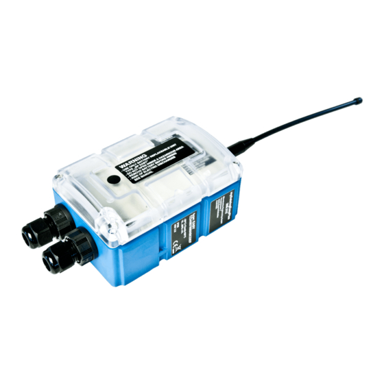
- Page 20 4.5 Overview Note: As the myDatalogEASY IoTmini is split into several components when delivered, it must be assembled before use (see "Assembling the myDatalogEASY IoTmini " on page 39). Front of the myDatalogEASY IoTmini Rear of the myDatalogEASY IoTmini (view of a device after assembly) (view of a device after assembly) 1 Antenna connector 3 Cable screw connection (cable diameter of 5-...
-
Page 21: Block Diagram
Chapter 4 General specifications 4.5.1 Block diagram Block diagram of the myDatalogEASY IoTmini It is a DC/DC converter with controllable output current. A power supply unit (e.g. PSU413D+ AP ) that is equipped with a rechargeable battery can thus be charged via the V in-/output. -
Page 22: Intended Use
Note: Detailed block diagrams of the most common power supply units are provided in chapter "Technical details about the energy supply" on page 62. 4.6 Intended use The portable, freely programmable measurement instrument is designed for determining, processing and transferring measurement data acquired via various industrial interfaces. The device can operate without mains power. -
Page 23: Device Labelling
Chapter 4 General specifications can optionally be initialised via the "rM2M_RegInit()" function and that is saved in the RAM. Its size can be specified during initialisation, although it is limited to a maximum of 1kB . The registration memory blocks are assigned to predefined purposes and are designed for storing device-specific data (see "Registration memory blocks"... -
Page 24: Installation Of Spare And Wear Parts
Note: These operating instructions are part of the device and must be available to the user at all times. The safety instructions contained therein must be observed. WARNING: It is strictly prohibited to disable the safety equipment or modify its mode of operation. 4.9 Installation of spare and wear parts Be advised that spare and accessory parts that have not been supplied by the manufacturer have also not been inspected or approved by the manufacturer. -
Page 25: Obligation Of The Operator
For safety and warranty reasons, all internal work on the instruments beyond from that involved in normal installation and connection, must be carried out only by qualified Microtronics personnel or persons or companies authorised by Microtronics . -
Page 26: Personnel Requirements
4.14 Personnel requirements Installation, commissioning and maintenance may only be completed by personnel who meet the following conditions: Qualified specialist personnel with the relevant training Authorised by the facility operator Note: Qualified personnel In the context of these instructions and the warnings on the product itself, individuals responsible for the setup, installation, commissioning and operation of the product must have gained relevant qualifications relating to their activities, including, for example: Training, instruction and authorisation to activate/deactivate, ground and label electric circuits and... -
Page 27: Chapter 5 Functional Principle
Chapter 5 Functional principle Chapter 5 Functional principle In the graphic below, all of the components that are part of the myDatanet are illustrated in grey. All other components must be provided/created by the customer. Functional principle 1 Client that uses a web browser to access the interface of the customer-specific server, which receives its data by means of a LoRaWAN connection. - Page 28 9 Customer-specific server that provides clients with their own interface. The customer-specific server obtains the data via the API interface of the myDatanet server (see "API" on page 187). 10 Client, on which a PC program is running, that obtains its data via the API interface of the myDatanet server (see "API"...
-
Page 29: Recommended Procedure
Chapter 5 Functional principle Application (device logic) The firmware of the myDatalogEASY IoTmini only manages the synchronisation of the measurement data and configurations between the myDatalogEASY IoTmini and myDatanet server. The application created by the customer must record the measurement values and create the data blocks that are to be saved. - Page 30 The internal data memory of the myDatalogEASY IoTmini is designed as a circular buffer with 8 sectors. If the entire memory (3MB ) is full, the sector with the oldest data is deleted fully before new data can be saved in this sector again.
-
Page 31: Memory Organisation
Chapter 5 Functional principle 5.3 Memory organisation Organisation of the myDatalogEASY IoTmini memory This memory block is only available if it was initialised via the "rM2M_RegInit()" function. The size of the PAWN binary must not exceed 256kB for the transmission to the myDatalogEASY IoTmini . If necessary, the data area of the PAWN binary can be compressed using a compiler instruction (#pragma amxcompress <0-3>). -
Page 32: Error Handling
5.4 Error handling The following transmission mechanisms have been integrated in the firmware to ensure that problems with the Device Logic can be diagnosed and resolved remotely. In the event that there is no Device Logic, a connection to the myDatanet server is established every 24h . This backup interval is set to 1h if an existing Device Logic has been deactivated due to an error being detected by the system. - Page 33 Chapter 5 Functional principle The "rM2M_RegGetString()", "rM2M_RegGetValue()", "rM2M_RegSetString()", "rM2M_RegSetValue()", "rM2M_RegDelValue()" and "rM2M_RegDelKey()" functions are available for accessing the registration memory blocks. 5.5.1 REG_SYS_FLASH If the site that is linked to the device was created from an application template (see myDatanet Server Manual 805002), the registration memory block contains the following fields: latestAppVersion The latest available version of the application template installed on the device [16-bit unsigned]...
-
Page 35: Chapter 6 Storage, Delivery And Transport
Check the shipment immediately upon receipt to ensure it is complete and intact. Immediately report any discovered transport damages to the delivering carrier. Also notify Microtronics Engineering GmbHin writing about this without delay. Report any incompleteness of the delivery to the responsible representative or directly to the company headquarters of the manufacturer within two weeks (see "Contact information"... - Page 36 6.3 Storage The following storage conditions must be observed: myDatalogEASY IoTmini Storage temperature -30...+85°C Humidity 15...90%rH PSU713 BP Operating temperature -20...+50°C Storage temperature +20...+25°C (300526) PSU413D+ AP Operating temperature -20...+60°C Charging temperature -20...+60°C (300524) Storage temperature 0... +30°C PSU413D AP Operating temperature -20...+60°C Charging temperature 0...+40°C...
- Page 37 Chapter 6 Storage, delivery and transport The following parties must observe these guidelines: Shipping and packaging company Haulage contractors Air carriers and ground handling service providers (only if the IATA guideline is applied) Security personnel (particularly if the IATA guideline is applied) When it comes to transporting hazardous goods, the most important tasks of the shipping and packaging company are: Classification / identification...
- Page 38 Support & Service Centre (see "Contact information" on page 209). The return shipment of the myDatalogEASY IoTmini must occur in the original packaging and with freight and insurance paid to Microtronics Engineering GmbH (see "Contact information" on page 209). Insufficiently cleared return shipments will otherwise not be accepted!
-
Page 39: Chapter 7 Installation
Chapter 7 Installation Chapter 7 Installation Important note: To prevent any damage to the device, the work described in this section of the instructions must only be performed by qualified personnel. 7.1 Dimensions Dimensions: width and height Dimensions: depth (view of a device after assembly) (view of a device after assembly) 7.2 Assembling the myDatalogEASY IoTmini Important note:... - Page 40 Components of the myDatalogEASY IoTmini 1 Connector plug (2x 2-pin, 2x 3-pin, 1x 6-pin) 4 myDatalogEASY IoTmini base unit 2 Power supply unit (not included in scope of 5 4x Delta PT M3.5x25 Torx 15 delivery) 3 2x cable screw connections (cable diameter of 5- 6 Housing cover 10 mm) Rev.
- Page 41 Chapter 7 Installation 1. Check that the content of the pack is complete. 2. Turn the locking nut of the cable screw connection clockwise (left-hand thread) to the stop to increase the distance between the locking nut and engagement hook and thus make it easier to insert the cable screw connection into the hole in the myDatalogEASY IoTmini base unit.
- Page 42 3. First of all thread the connection cables of your sensors, actuators and, if necessary, the supply or charging voltage through one of the cable screw connections in accordance with the following figure, and then through one of the holes in the myDatalogEASY IoTmini base unit. Then connect the cables to the connector plugs as described in chapter "Connecting the sensors, actuators and power supply"...
- Page 43 Chapter 7 Installation 5. Tighten the locking nut by turning it clockwise (left-hand thread). Important note: Ensure that the seal is clean and intact before tightening. Remove any impurities and/or dirt. The manufacturer shall not be liable for any damage to the device caused by leaky or faulty seals.
- Page 44 10. Close the housing cover. The best option is to tighten the four screws crosswise (torque 0,5Nm; At the first screw 0,7Nm because the threads have to be shaped into the base part first.) so that the housing cover is positioned evenly. Important note: Ensure that the seals are clean and intact before closing the housing cover.
- Page 45 Chapter 7 Installation 7.3 Installing the myDatalogEASY IoTmini Important note: Ensure installation is completed correctly. Comply with existing legal and/or operational directives. Improper handling can cause injuries and/or damage to the devices. The myDatalogEASY IoTmini must not be operated in the field with the lid open. The pressure compensation must be protected against contamination.
-
Page 46: Wall Mounting
7.3.1 Wall mounting For wall mounting the optional "Universal bracket for housing myDatanet 86x126 (206.640)" equipment is required. Step 1 of the wall mounting Step 2 of the wall mounting 1 myDatalogEASY IoTmini 3 Assembly loop (included in the delivery scope of 206.640) 2 Delta PT M3.5x8 Torx 15 (included in the delivery 4 Raised head tapping screw 3.5x32 (included in... - Page 47 Chapter 7 Installation 7.3.2 Top-hat rail assembly The "DIN rail mounting set for myDatanet housing 86x126 (206.634)" equipment is required for the top-hat rail assembly. Step 1 of the top-hat rail assembly Step 2 of the top-hat rail assembly 1 myDatalogEASY IoTmini 3 Assembly loop (included in the scope of delivery of 206.634) 2 Delta PT M3.5x8 Torx 15 (included in the scope of...
-
Page 48: Pipe Assembly
7.3.3 Pipe assembly The optional "Pipe mounting kit for myDatanet housing 86x126 (206.660)" equipment is required for the pipe assembly. Step 1 of the pipe assembly Step 2 of the pipe assembly 1 myDatalogEASY IoTmini 3 Assembly loop (included in the scope of delivery of 206.660) 2 Delta PT M3.5x8 Torx 15 (included in the scope of 4 Cable binder (included in the scope of delivery of... -
Page 49: Safety Instructions For The Cabling
Chapter 7 Installation 7.4 Safety instructions for the cabling Important note: To avoid any damage, always switch off the voltage supply to the device when performing electrical connections. When connections are made to the myDatalogEASY IoTmini , the following warnings and information must be observed, in addition to the warnings and information found in the individual chapters on the installation. -
Page 50: Electrical Installation
7.4.1 Information on preventing electrostatic discharges (ESD) Important note: Maintenance procedures that do not require the device to be connected to the power supply should only be performed once the device has been disconnected from the mains power supply to minimise hazards and ESD risks. The sensitive electronic components inside the device can be damaged by static electricity, which can impair the device performance or even cause the device to fail. - Page 51 Chapter 7 Installation Connection of the sensors and power supply (view without power supply unit) 1 Mini-B USB (only for debug and script update) 3 Main terminal block (split into 2x 2-pin, 2x 3-pin, 1x 6-pin) 2 RS232 interface (7-pin JST connector) 4 Cable screw connection (cable diameter of 5- 10 mm) Assignment of the RS232 interface...
- Page 52 Assignment of the main terminal block V IN External supply or charging voltage Ground (external supply or charging voltage) Isolated switch contact VEXT Switchable sensor supply (3,3V ) Ground UI 1 Universal input 1 UI 2 Universal input 2 UI3/A+ Universal input 3 / RS485 A UI 4/B- Universal input 4 / RS485 B Ground...
- Page 53 Chapter 7 Installation 6. Connect the antenna (see "Connecting the LoRa antenna" on page 54). The antenna is not included in the scope of delivery and must be ordered separately. 7. Insert the power supply unit. The following step is not mandatory. 8.
- Page 54 The following step is only necessary if you are using an external supply or charging voltage. 11. Now switch on the external supply or charging voltage. Note: If you are using a power supply unit without an integrated energy store, the external supply or charging voltage must be switched on before the optional step during which the connection to the server is tested.
- Page 55 Chapter 7 Installation 3. Connect the antenna extension or antenna directly to the antenna connector of the myDatalogEASY IoTmini (see "Overview" on page 20) Important note: Do not apply too much force when tightening the antenna. Do not use any tools to tighten the antenna or antenna extension; only tighten it manually. 4.
- Page 56 7.5.3.4 Standard digital modes (PWM, frequency, digital, counter) General <0,99V High >2,31V Load 10k086 Measurement 1...99% range 100Hz Minimum pulse length Frequency Measurement 1...1000Hz range Counter Minimum pulse length 7.5.4 Technical details about the PT100/1000 interface The interface for the external temperature sensor automatically detects whether a PT100 or PT1000 is being used.
- Page 57 Chapter 7 Installation The 120Ω load resistance between RS485 A and B can be activated via the "RS485_Init()" function. Schematic diagram of the switchable load resistance Note: Additional explanation regarding the connection of two RS485 bus participants Schematic diagram: Connection of two RS485 bus participants A problem occurs if there is no connection between the GND potentials of the sender and recipient.
- Page 58 Explanations regarding the functionality of the DeviceConfig configuration program is provided in the manual for the DeviceConfig ("myDatanetDeviceConfig Manual " 805004). Access to the web-based development environment rapidM2M Studio is included in the Microtronics Partner Program, for which you can register free of charge at the following address: https://partner.microtronics.com...
- Page 59 Chapter 7 Installation 7.5.8 Technical details about the outputs 7.5.8.1 Switchable sensor supply VOUT Note: The switchable sensor supply output is short-circuit-proof. The output voltage can be varied in the range of 5...24V using the Device Logic (see "Vsens_On()"). Output voltage characteristics subject to the load current for VOUT = 5V Output voltage characteristics subject to the load current for VOUT = 12V Rev.
- Page 60 Output voltage characteristics subject to the load current for VOUT = 15V Output voltage characteristics subject to the load current for VOUT = 24V 7.5.8.2 Switchable sensor supply VEXT Note: The switchable sensor supply output is short-circuit-proof. The switchable sensor supply VEXT is applied to the main terminal block (see "Connecting the sensors, actuators and power supply"...
- Page 61 Chapter 7 Installation 7.5.8.3 Switchable sensor supply VEXT RS232 Note: The switchable sensor supply output is short-circuit-proof. The switchable sensor supply VEXT is applied to the connector of the RS232 interface (see RS232 "Connecting the sensors, actuators and power supply" on page 50). 3,3V 180mA 7.5.8.4 Isolated switch contact (NO, CC)
- Page 62 When an external supply or charging voltage (V IN) is used, the charge control ensures that the rechargeable battery of the power supply unit is charged. The following operating states are possible: Active energy saving mode (i.e. Device Logic inactive) or no Device Logic installed: The charge control tries to charge the rechargeable battery to 3,8V or to maintain the voltage at this level.
- Page 63 Chapter 7 Installation V IN 12...32VDC Power consumption typ. <1mW (without sensors) max. 12W Reverse voltage protection applies to continuous operation if the possibly available rechargeable battery of the power supply unit is fully charged A selection of compatible power supplies is included in the chapter "Charging devices and power supply units"...
- Page 64 7.5.10.3 PSU713 BP (300526) V IN Not required Protective circuit (V IN) Capacity 13Ah 93,6Wh Type Li-SOCl2 Rechargeable Nominal voltage 7,2V Block diagram of the PSU713 BP Operating temperature -20...+50°C Charging temperature Storage temperature +20...+25°C 7.5.10.4 PSU DC (300529) V IN Required Protective circuit (V IN) DC-Protection circuit...
- Page 65 Chapter 7 Installation 7.5.10.6 PSU DC+ (300798) V IN Required Protective circuit (V IN) DC-Protection circuit Capacity 900mAh 3,33Wh Type Li-Po Rechargeable Nominal voltage 3,7V Block diagram of the PSU DC+ Operating temperature -20...+60°C Charging temperature 0...+40°C Storage temperature 0... +35°C 7.5.11 Technical details about the system time The myDatalogEASY IoTmini is equipped with a hardware real-time clock that has its own buffer battery with an expected service life of >10 years.
-
Page 67: Chapter 8 Initial Start-Up
Read this manual carefully and completely in order to ensure the proper functioning of the myDatalogEASY IoTmini . Contact Microtronics Engineering GmbH(see "Contact information" on page 209) if anything is unclear or if you encounter difficulties with regard to installation, connection or configuration. - Page 68 The following work should be completed in the office before you go to the future location of the device: 1. If necessary, create a customer on the myDatanet server (see "myDatanet Server Manual " 805002). 2. Within the selected customer, create a site/application for operation on the myDatanet server (see "Creating the site"...
-
Page 69: Testing Communication With The Device
Chapter 8 Initial Start-Up The following work is completed directly at the location of the device: 8. Complete all of the steps detailed in the chapter "Assembling the myDatalogEASY IoTmini " on page 9. Check whether the connection to the myDatanet server has worked correctly (see "Testing communication with the device"... - Page 70 5. Wait until the measurement instrument list indicates that the device is connected to the server (rotating arrows). With the exception of the "Online" connection type (see "rM2M_TxSetMode()"), the time during which the myDatalogEASY IoTmini is connected to the server is very short. It can therefore also be checked whether the time stamp of the last connection (under the green status symbol) has been updated.
-
Page 71: Chapter 9 User Interfaces
Chapter 9 User interfaces Chapter 9 User interfaces The configuration of the myDatalogEASY IoTmini is carried out via the web interface on the myDatanet server (see "User interface on the myDatanet server" on page 72), which your responsible sales partner will provide to you. -
Page 72: Site Configuration
controlled by the "Led_On()", "Led_Off()", "Led_Blink()" , "Led_Flash()" and "Led_Flicker()" Device Logic functions. Operating states (two-colour LED controlled by the firmware) Two-colour LED Colour Description Flickering Green Establishing connection Lights up Green GPRS connection or USB connection established Normal operation/script processing until the next transmission 9.2 User interface on the myDatanet server 9.2.1 Site configuration Note: Depending on the respective user level, some of the configuration fields mentioned in the following sub-... - Page 73 Chapter 9 User interfaces 9.2.1.3 Control Note: This configuration section is not visible if this site was created based on an IoT application (see "myDatanet Server Manual " 805002). Device logic Device logic deactivated type Pawn Activates device logic processing and informs the myDatalogEASY IoTmini that the device logic is a "Pawn script".
- Page 74 9.2.1.5 Alarm settings Acknowledgement Standard The global server setting is used to determine whether alarms must be acknowledged automatically or manually. automatic Alarms are acknowledged automatically as soon as all of the messages have been sent. If SMS that have a tariff with a delivery confirmation function have also been sent, acknowledgement is provided after delivery confirmation.
- Page 75 Chapter 9 User interfaces 9.2.1.6 Basic settings Time zone Regional settings (not relevant for raw measurement data as this is stored in UTC) Daylight saving time Configuration for automatic time adjustment Standard The configuration for the time adjustment is adopted by the global server setting.
-
Page 76: Device Configuration
9.2.2 Device configuration Note: Several of the configuration fields in the following sub chapters may possibly be hidden depending on the respective user level. In this case, contact the myDatanet server administrator. You can reach the input screen for configuring the device by clicking on the serial number in the site list (see "myDatanet Server Manual "... - Page 77 Chapter 9 User interfaces Device Logic sync Productive If the Device Logic installed on the device and saved on the server do not match, the Device Logic saved on the server is loaded in to the device. Development (sync) The Device Logic on the device and server are synchronised. The one with the latest time stamp is transferred to the other one.
- Page 79 10.1 General Access to the web-based development environment rapidM2M Studio is included in the Microtronics Partner Program, for which you can register free of charge at the following address: https://partner.microtronics.com...
- Page 80 10.2 Prerequisites Interfaces 1 x USB Operating system Windows 7 Windows 10 (recommended) MacOS 10.12 or higher Linux (Fedora 32, Ubuntu 20.04, Archlinux 2020.06.01) Internet Required connection Required disk No installation required space Browser Google Chrome only Rev. 01...
- Page 81 Chapter 11 myDatanet server Chapter 11 myDatanet server Note: All of the screenshots show version 47.10 of the myDatanet server using the standard colour scheme. Newer versions may include minor changes to the appearance of the server. 11.1 Recommended procedure 11.1.1 Creating the site Detailed instructions on creating a new site are provided in myDatanet Server Manual (805002).
- Page 83 Chapter 12 Device Logic (Pawn) Chapter 12 Device Logic (Pawn) 12.1 General The following chapter describes the functionality of the device logic. The programming language used is "Pawn" (previously SMALL), a scripting language similar to C that runs on embedded systems. Additional, more detailed information is provided on the developer's website: http://www.compuphase.com/pawn/pawn.htm.
- Page 84 12.2 Compiler options Compressing the pawn program code // The parameter is used to specify which of the sections should be // compressed // 0: no compression (default) // 1: DATA // 2: DATA and CODE // 3: DATA, CODE and TABLES #pragma amxcompress <0-3>...
- Page 85 Chapter 12 Device Logic (Pawn) 12.3.2 Timer, date & time 12.3.2.1 Arrays with symbolic indices TrM2M_DateTime Detailed breakdown of the date and time // year Year specified relates to the 21st century, i.e. 14 refers to the year 2014 // month Month // day // hour...
- Page 86 native rM2M_GetDate(&year=0, &month=0, &day=0, timestamp=0); If no time stamp was transferred (timestamp=0), the date (year, month, day) is determined for the current system time (in UTC). Alternatively, the date (year, month, day) is determined for the transferred time stamp. Parameter Explanation year Variable to store the year - OPTIONAL...
- Page 87 Chapter 12 Device Logic (Pawn) native rM2M_SetDateTime(datetime[TrM2M_DateTime], flags=0); Sets the system date and time to the values contained in the transferred structure Parameter Explanation datetime Structure that contains a detailed breakdown of the date and time (see "TrM2M_ DateTime" in chapter "Arrays with symbolic indices" on page 85). .timestamp = 0: The values contained in .year, .month, .day, .hour, .minute and .second are used to set the date/time.
- Page 88 native rM2M_TimerAdd(funcidx); Generates a new 1s timer Parameter Explanation funcidx Index of the public function that should be called up following expiry of the timer Type of function: public func(); Explanation Return value OK, if successful ERROR if no valid index was transferred, in the event of an internal error or if no further timers can be created (maximum number reached) <...
- Page 89 Chapter 12 Device Logic (Pawn) native rM2M_TimerAddExt(funcidx, bool:cyclic, time); Generates a new ms timer Parameter Explanation funcidx Index of the public function that should be called up following expiry of the timer Type of function: public func(); cyclic Setting for the behaviour following expiry of the timer interval: true: The timer must be restarted following expiry of the interval.
- Page 90 12.3.3 Uplink 12.3.3.1 Constants Configuration flags for the rM2M_CfgInit() function RM2M_CFG_VOLATILE = 0b00000001, // volatile storage (RAM) 12.3.3.2 Callback functions public func(const data[], len, timestamp); Function to be provided by the script developer, that is called once a data record has been read (using the "rM2M_ReadData()"...
- Page 91 Chapter 12 Device Logic (Pawn) 12.3.3.3 Functions native rM2M_LiveData(const data{}, len); Transmits a data record as live data to the server. Calling this function is only permissible if the device is in "online" mode and an active connection to the server is established. Use the "rM2M_Pack", "rM2M_ SetPacked"...
- Page 92 native rM2M_ReadData(recidx, funcidx); Reads out a data record saved in the internal flash and then calls up the function for which the index was transferred. Parameter Explanation recidx Index of the data record to be read (-1 = last/current data record, -2 = penultimate data record, ..
- Page 93 Chapter 12 Device Logic (Pawn) native rM2M_CfgWrite(cfg, pos, const data{}, size); Saves the transferred data block at the specified position in a configuration memory block. Note that the configuration memory block is either saved in the RAM in a volatile manner (Bit0 = RM2M_CFG_ VOLATILE) or in the FLASH in a non-volatile manner (Bit0 = 0, default) depending on the type of storage selected via the "rM2M_CfgInit"...
- Page 94 native rM2M_CfgRead(cfg, pos, data{}, size); Reads a data block from the specified position in a configuration memory block. The function is also informed which of the 10 available memory blocks in the internal flash memory should be read. Use the "rM2M_Pack", "rM2M_GetPacked"...
- Page 95 Chapter 12 Device Logic (Pawn) native rM2M_CfgOnChg(funcidx); Specifies the function that should be called if one of the configuration memory blocks has changed Parameter Explanation funcidx Index of the public function that should be called if the configuration has changed Type of function: public func(cfg);...
- Page 96 Numbers of the temperature sensor interfaces TEMP_CHANNEL1 = 0, // PT100/1000 interface 1 //Number of temperature sensor interfaces, with which the myDatalogEASY IoTmini //equipped TEMP_NUM_CHANNELS = 1, Configuration of the external temperature measurement (PT100/1000) Configuration options for the Temp_Init() function TEMP_MODE_SINGLE_CONV = 0, // single conversion mode TEMP_MODE_CONT_CONV = 1,...
- Page 97 Chapter 12 Device Logic (Pawn) 12.3.4.3 Functions native Temp_Init(temp, mode); The temperature is only measured once after this function is called if single conversion mode has been activated (mode = TEMP_MODE_SINGLE_CONV). The measurement value can be read out by the "Temp_GetValue"...
- Page 98 native Temp_GetValue(temp, &value); Reads the temperature measurement value for the specified PT100/1000 interface from the temperature module Parameter Explanation temp Number of the PT100/1000 interface; is always 0 on the myDatalogEASY IoTmini value Variable to store the temperature measurement value to be read out. The temperature measurement value is saved in the temperature module in [0.1°C].
- Page 99 Chapter 12 Device Logic (Pawn) 12.3.5 Encoding 12.3.5.1 Constants Configuration flags for the rM2M_Pack() function RM2M_PACK_GET = 0b00000001, // Value should be read (get packed) RM2M_PACK_BE = 0b00000010, // Use "Big endian" format RM2M_PACK_U8 = 0b00010000, // 8-bit unsigned RM2M_PACK_S8 = 0b10010000, // 8-bit signed RM2M_PACK_U16 = 0b00100000, // 16-bit unsigned...
- Page 100 12.3.5.2 Functions native rM2M_SetPacked(data{}, pos, &{Float,Fixed,_}:value, size=4, bool:bigendian=false); Writes the transferred value to a specified position in an array Important note: Although this function will still be supported for the purpose of downward compatibility, it should no longer be used for new projects as the unsigned data types might lead to problems.
- Page 101 Chapter 12 Device Logic (Pawn) native rM2M_SetPackedB(data{}, pos, const block[], size); Writes the transferred data block to the specified position in an array Parameter Explanation data Array that should be used as a data area for a data record or a configuration Byte offset within the array to determine the position where the data block should be written block...
- Page 102 native rM2M_GetPacked(const data{}, pos, &{Float,Fixed,_}:value, size=4, bool:bigendian=false); Supplies the value that is located at the specified position in an array Important note: Although this function will still be supported for the purpose of downward compatibility, it should no longer be used for new projects as the unsigned data types might lead to problems.
- Page 103 Chapter 12 Device Logic (Pawn) native rM2M_GetPackedB(const data{}, pos, block[], size); Reads a data block that is located at the specified position in an array Parameter Explanation data Array that should be used as a data area for a data record or a configuration Byte offset within the array to determine the position from which the data should be read block...
- Page 104 native rM2M_Pack(const data{}, pos, &{Float,Fixed,_}:value, type); Function to access packed data. If the Bit0 (RM2M_PACK_GET) of the "type" parameter was set, the function returns the value that is located at the specified position in the array. Otherwise the function writes the transferred value to the specified position in the array. Parameter Explanation data...
- Page 105 Chapter 12 Device Logic (Pawn) 12.3.6 RS232, RS485 12.3.6.1 Constants Configuration of the RS232 interface Configuration flags for the RS232_Init() function RS232_1_STOPBIT = 0b0000000000000001, // 1 stop bit RS232_2_STOPBIT = 0b0000000000000010, // 2 stop bit RS232_PARITY_NONE = 0b0000000000000000, // no parity RS232_PARITY_ODD = 0b0000000000000100, // odd parity RS232_PARITY_EVEN...
- Page 106 public func(const data{}, len); Function to be provided by the script developer, that is called when characters are received via the RS485 interface Parameter Explanation data Array that contains the received data Number of received bytes Rev. 01...
- Page 107 Chapter 12 Device Logic (Pawn) 12.3.6.3 Functions native RS232_Init(rs232, baudrate, mode, funcidx); Initialises the RS232 interface Parameter Explanation rs232 Number of the RS232 interface; is always 0 for the myDatalogEASY IoTmini Note: You can also use the predefined constant "RS232_ITF1" for this parameter.
- Page 108 native RS232_Close(rs232); Closes the RS232 interface Parameter Explanation rs232 Number of the RS232 interface; is always 0 for the myDatalogEASY IoTmini Note: You can also use the predefined constant "RS232_ITF1" for this parameter. Explanation Return value OK, if successful ERROR_FEATURE_LOCKED, if the specified interface on the device is not released <...
- Page 109 Chapter 12 Device Logic (Pawn) native RS232_Setbuf(rs232, rxbuf{}, rxlen, txbuf{}, txlen); Provides the firmware with one buffer for sending and one for receiving characters via the RS232 interface from the RAM area reserved for the Device Logic. When this function is called, the system switches from the 256 byte buffers integrated in the firmware to the transferred buffers.
- Page 110 native RS485_Init(rs485, baudrate, mode, funcidx); Initialises the RS485 interface Parameter Explanation rs485 Number of the RS485 interface; is always 0 for the myDatalogEASY IoTmini Note: You can also use the predefined constant "RS485_ITF1" for this parameter. baudrate Baud rate to be used. Observe the valid limits for the device being used (see "Technical details about the RS485 interface"...
- Page 111 Chapter 12 Device Logic (Pawn) native RS485_Close(rs485); Closes the RS485 interface Parameter Explanation rs485 Number of the RS485 interface; is always 0 for the myDatalogEASY IoTmini Note: You can also use the predefined constant "RS485_ITF1" for this parameter. Explanation Return value OK, if successful ERROR_FEATURE_LOCKED, if the specified interface on the device is not released...
- Page 112 native RS485_Setbuf(rs485, rxbuf{}, rxlen, txbuf{}, txlen); Provides the firmware with one buffer for sending and one for receiving characters via the RS485 interface from the RAM area reserved for the Device Logic. When this function is called, the system switches from the 256 byte buffers integrated in the firmware to the transferred buffers. Important note: If necessary, this function may need to be called before the initialisation of the RS485 interface via the "RS485_Init()"...
- Page 113 Chapter 12 Device Logic (Pawn) 12.3.7 LoRa 12.3.7.1 Constants Configuration of the UART interface that is connected to the LoRa module Configuration flags for the LoRa_Init() function LORA_1_STOPBIT = 0b0000000000000001, // 1 Stop bit LORA_2_STOPBIT = 0b0000000000000010, // 2 Stop bit LORA_PARITY_NONE = 0b0000000000000000, // no parity LORA_PARITY_ODD...
- Page 114 12.3.7.3 Functions native LoRa_Init(LoRa, baudrate, mode, funcidx); Initialises the UART interface that is connected to the LoRa module Parameter Explanation LoRa Number of the UART interface that is connected to the LoRa module; for the myDatalogEASY IoTmini always 0 baudrate Baud rate to be used mode Bit 0...1 1 = 1 stop bit...
- Page 115 Chapter 12 Device Logic (Pawn) native LoRa_Close(LoRa); Closes the UART interface that is connected to the LoRa module Parameter Explanation LoRa Number of the UART interface that is connected to the LoRa module; for the myDatalogEASY IoTmini always 0 Explanation Return value OK, if successful ERROR_FEATURE_LOCKED if data transmission via LoRaWAN is not activated on the device...
- Page 116 native LoRa_Setbuf(LoRa, rxbuf{}, rxlen, txbuf{}, txlen); Provides the firmware with one buffer for sending and one for receiving characters via the UART interface, that is connected to the LoRa module, from the RAM area reserved for the device logic. When this function is called, the system switches from the 128 byte buffers integrated in the firmware to the transferred buffers.
- Page 117 Chapter 12 Device Logic (Pawn) 12.3.8 Registry 12.3.8.1 Constants Indices of the registration memory blocks that can be accessed via the "rM2M_RegGetString()", "rM2M_RegGetValue()", "rM2M_ RegSetString()", "rM2M_RegSetValue()", "rM2M_RegDelValue()" and "rM2M_RegDelKey()" functions. Detailed information on the registration memory blocks is provided in chapter "Registration memory blocks"...
- Page 118 12.3.8.2 Callback functions public func(reg); Function to be provided by the script developer, that is called up if the registration has changed Parameter Explanation Index of the registration memory block (see "Indices of the registration memory blocks" in chapter "Constants" on page 117) that has been changed 12.3.8.3 Functions native rM2M_RegInit(reg, flags, data{}, len=sizeof data);...
- Page 119 Chapter 12 Device Logic (Pawn) native rM2M_RegGetString(reg, const name[], string[], len=sizeof string); Reads a character string from a registration memory block. Detailed information on the registration memory blocks is provided in chapter "Registration memory blocks" on page 32. Parameter Explanation Index of the registration memory block (see "Indices of the registration memory blocks"...
- Page 120 native rM2M_RegSetString(reg, const name[], const string[]); Writes a character string into a registration memory block. Detailed information on the registration memory blocks is provided in chapter "Registration memory blocks" on page 32. Parameter Explanation Index of the registration memory block (see "Indices of the registration memory blocks"...
- Page 121 Chapter 12 Device Logic (Pawn) native rM2M_RegDelValue(reg, const name[]); Searches for an entry based on its name and sets the value of this entry (regardless of whether it is a string or value) to "null". Detailed information on the registration memory blocks is provided in chapter "Registration memory blocks"...
- Page 122 native rM2M_RegOnChg(funcidx); Specifies the function that should be called up if one of the registration memory blocks has changed. Detailed information on the registration memory blocks is provided in chapter "Registration memory blocks" on page 32. Parameter Explanation funcidx Index of the public function that should be called up if the registration has changed Type of function: public func(reg);...
- Page 123 Chapter 12 Device Logic (Pawn) NMEA quality indicator RM2M_NMEA_FIX_NOK = 0, // invalid/no fix RM2M_NMEA_FIX_GPS = 1, // Non-differential GPS fix RM2M_NMEA_FIX_DGPS = 2, // Differential GPS fix RM2M_NMEA_FIX_PPS = 3, // Precise positioning service (PPS) RM2M_NMEA_FIX_RTK = 4, // Real time kinematic (RTK) RM2M_NMEA_FIX_FLOATRTK = 5, // Float real time kinematic RM2M_NMEA_FIX_EST...
- Page 124 12.3.9.3 Functions native rM2M_SetPos(Lat, Long, Elev, Qual, SatUsed); Saves the GPS position information in the device. A historical record is not maintained. This means that the current position information always overwrites the last known position. The information is transmitted to the myDatanet server and can, for example, be read out via the API (see "API" on page 187).
- Page 125 Chapter 12 Device Logic (Pawn) native rM2M_DecodeNMEA(const sentence{}, data[], len=sizeof data); Decodes a transferred NMEA data record Parameter Explanation sentence NMEA data record from a GPS receiver starting with the '$' character. Important note: The strings must be terminated ('\0') immediately after the checksum.
- Page 126 native rM2M_SetPosNMEA(const Sentence{}); Takes the GPS position information from the transferred NMEA data record and saves it in the device. A historical record is not maintained. This means that the current position information always overwrites the last known position. The information is transmitted to the myDatanet server and can, for example, be read out via the API (see "API"...
- Page 127 Chapter 12 Device Logic (Pawn) native rM2M_GetPos(&Lat, &Long, &Elev, &Qual=0, &SatUsed=0); Reads out the GPS position information saved to the device Parameter Explanation Variable to store the geographical latitude in degrees (resolution: 0.000001°) -90 000 000 = South pole 90° south 0 = Equator +90 000 000 = North pole 90°...
- Page 128 12.3.10 Math Helpful constants Definition Value Description 2.7182818284590452354 M_LOG2E 1.4426950408889634074 M_LOG10E 0.43429448190325182765 M_LN2 0.69314718055994530942 ln 2 M_LN10 2.30258509299404568402 ln 10 M_PI 3.14159265358979323846 π M_PI_2 1.57079632679489661923 π/2 M_PI_4 0.78539816339744830962 π/4 M_1_PI 0.31830988618379067154 1/π M_2_PI 0.63661977236758134308 2/π M_2_SQRTPI 1.12837916709551257390 2/sqrt(π) M_SQRT2 1.41421356237309504880 sqrt(2) M_SQRT1_2 0.70710678118654752440...
- Page 129 Chapter 12 Device Logic (Pawn) native max(value1, value2); Supplies the larger of the two transferred values Parameter Explanation value1 Two values of which the larger one is to be determined value1 Explanation Return value The larger of the two transferred values native clamp(value, min=cellmin, max=cellmax);...
- Page 130 native Float:asin(Float:x); Arcsine(x) in the range [-π/2, π/2], x element of [-1, 1] native Float:acos(Float:x); Arccosine(x) in the range [0, π], x element of [-1, 1] native Float:atan(Float:x); Arctangent(x) in the range [-π/2, π/2] native Float:atan2(Float:y, Float:x); Arctangent(y/x) in the range [-π, π] native Float:sinh(Float:x);...
- Page 131 Chapter 12 Device Logic (Pawn) 12.3.11 Char & String Note: You require the following include file to be able to use the functions in this chapter: #include <string> The mode of operation of the following functions essentially corresponds to that of the standard ANSI-C implementation: native strlen(const string[]);...
- Page 132 native strcat(dest[], const source[], maxlength=sizeof dest); Adds the source character string to the dest character string (including '\0') Parameter Explanation dest Array to store the result. This array already comprises one character string to which the source character string should be added. source Character string that should be added to the character string included in the array dest...
- Page 133 Chapter 12 Device Logic (Pawn) native strrchr(const string[], char); Searches for a character (last occurrence) in a character string Parameter Explanation string Character string that should be searched char Character that the search is looking for Explanation Return value -1, if the character that the search is looking for is not included in the character string Array index for the character that the search is looking for (last character occurring in the character string)
- Page 134 native strpbrk(const string1[], const string2[]); Searches the array index of the first character that is also included in the character string of permitted characters Parameter Explanation string1 Character string that should be searched string2 Character string of permitted characters Explanation Return value -1, if the character that the search is looking for is not included in the character string...
- Page 135 Chapter 12 Device Logic (Pawn) native Float: atof(const string[]); Converts a character string into a float Parameter Explanation string Character string that is to be converted Explanation Return value Float for which the numerical value corresponds to the character string native tolower(c);...
- Page 136 12.3.12 CRC & hash 12.3.12.1 Arrays with symbolic indices TMD5_Ctx Context structure for the MD5 calculation // init After being set to "0", the context structure can be used to calculate a new hash. If a calculation should be implemented by calling up the "MD5" function repeatedly, write access must not be granted for this element.
- Page 137 Chapter 12 Device Logic (Pawn) native MD5(data{}, len, hash{16}, ctx[TMD5_Ctx] = [0]); Calculates the MD5 hash for the transferred data. If the hash for a data block should be calculated by calling up this function several times (e.g. when receiving data in blocks), then the same context structure must be transferred every time the function is called up.
- Page 138 TrM2M_Id Information for identifying the module/device // string rapidM2M module identification (e.g. "rapidM2M EasyIoT HW1.1") // module rapidM2M module type (e.g. "EasyIoT") // hwmajor Hardware: Major version number // hwminor Hardware: Minor version number // sn Device serial number (binary) in BIG endian format E.g.: "010146AF251CED1C"...
- Page 139 Chapter 12 Device Logic (Pawn) native exists(const name[]); checks whether the required rapidM2M API function is supported by the device firmware Parameter Explanation name Name of the required rapidM2M API function Explanation Return value true, if the function is available false, if the device firmware does not support the function native loadmodule(mod{});...
- Page 140 native rtm_stop(measurement[TRTM_Data]); Stops the runtime measurement and calculates the time in [ms] since the "rtm_start()" function was called up and the pawn instructions executed since then. The determined values are written in the ".runtime" and ".instructions" elements of the transferred structure to record the information regarding a runtime measurement.
- Page 141 Chapter 12 Device Logic (Pawn) native CalcTable(key, &value, const table[][TablePoint], size = sizeof table); Searches for a certain value in the "key" column of the transferred reference point table and supplies the relevant value from the "value" column in the table. If the searched value is between two reference points, the returned value is interpolated linearly between the two adjacent values in the "value"...
- Page 142 native rM2M_GetId(id[TrM2M_Id], len=sizeof id); Provides the information to identify the module/device Parameter Explanation Structure for storing the information to identify the module/device (see "TrM2M_ Id" in chapter "Arrays with symbolic indices" on page 137) Size (in cells) of the structure to store the information - OPTIONAL Explanation Return value Size (in cells) of the structure used to store the information...
- Page 143 Chapter 12 Device Logic (Pawn) native getarg(arg, index=0); Supplies the value of the argument Parameter Explanation The sequence number of the argument. Use 0 for the first argument. index Index if "arg" refers to an array Explanation Return value This function supplies an argument from a variable argument list. If the argument is an array, the "index"...
- Page 144 12.3.14 Console native print(const string[]); Prints the specified string to the standard output Parameter Explanation string The character string to be issued. This can include escape sequences. Explanation Return value native printf(const format[], {Float,Fixed,_}:...); Prints the transferred format string to the standard output. The mode of operation of the functions corresponds to that of the standard ANSI-C implementation.
-
Page 145: Universal Inputs
Chapter 12 Device Logic (Pawn) 12.3.15 Universal inputs Note: You require the following include file to be able to use the functions in this chapter: #include <ui> 12.3.15.1 Constants Selection of the mode for an universal input Input modes for the UI_Init() function UI_CHT_SI_NONE = 0, // Deactivated... - Page 146 12.3.15.2 Functions native UI_Init(channel, mode, filtertime); Initialises an universal input (UI 1 - UI 4 ). The sample rate for acquiring the measurement value is configured by the "UI_SetSampleRate" function. Calling up the "UI_SetSampleRate" function is only necessary, if the default sample rate setting of 16Hz (62,5ms) is not suitable for your application. Detailed information on the universal inputs is provided in chapter "Technical details about the universal inputs"...
- Page 147 Chapter 12 Device Logic (Pawn) native UI_Close(channel); Deactivates an universal input (UI 1 - UI 4 ). Detailed information on the universal inputs is provided in chapter "Technical details about the universal inputs" on page 55. Note: The energy consumption decreases with each universal input that is deactivated. Parameter Explanation channel...
- Page 148 native UI_SetSampleRate(samplerate); Sets the sample rate for the measurement value acquisition at the universal inputs. The specified setting is always valid for all of the universal inputs. Special settings for individual universal inputs are not possible. The default value of the sample rate is 16Hz (62,5ms) . Detailed information on the universal inputs is provided in chapter "Technical details about the universal inputs"...
- Page 149 Chapter 12 Device Logic (Pawn) 12.3.16 Outputs 12.3.16.1 Constants Numbers of the digital outputs DIGOUT_CHANNEL1 = 0, // isolated switch contact 1 //Number of digital outputs, with which the myDatalogEASY IoTmini is equipped DIGOUT_NUM_CHANNELS = 1, Selection of the output voltage for the switchable sensor supply VOUT Configuration options for the Vsens_On() function VSENS_15V = 0, // 14,7V at I...
- Page 150 native Vsens_Off(); Deactivates the switchable sensor supply VOUT. Detailed information on the switchable sensor supply is provided in chapter "Switchable sensor supply VOUT" on page 59. Explanation Return value OK, if successful < OK, if an error occurs (see "Return codes for general purposes" in chapter "Constants"...
- Page 151 Chapter 12 Device Logic (Pawn) native DigOut_Init(digout, mode, cfg1 = -1, cfg2 = -1); Initialises the isolated switch contact (NO, CC). The mode is selected via the "mode" parameter. The meaning of the "cfg1" and "cfg2" parameters is dependent on the selected mode. Detailed information on the isolated switch contact is provided in chapter "Isolated switch contact (NO, CC)"...
- Page 152 Explanation Return value OK, if successful < OK, if an error occurs (see "Return codes for general purposes" in chapter "Constants" on page 84) native DigOut_Close(digout); Deactivates the isolated switch contact (NO, CC). Detailed information on the isolated switch contact is provided in chapter "Isolated switch contact (NO, CC)"...
- Page 153 Chapter 12 Device Logic (Pawn) native DigOut_SetValue(digout, value); Specifies the setpoint for the isolated switch contact (NO, CC). The meaning of the "value" parameter is dependent on the mode of the isolated switch contact selected via the "DigOut_Init" function. Detailed information on the isolated switch contact is provided in chapter "Isolated switch contact (NO, CC)"...
- Page 154 native RS232_3V3_On(); Activates the switchable 3,3V supply voltage VEXT . Detailed information on the switchable 3,3V RS232 supply voltage VEXT is provided in chapter "Switchable sensor supply VEXTRS232" on page 61. RS232 Explanation Return value OK, if successful < OK, if an error occurs (see "Return codes for general purposes" in chapter "Constants"...
- Page 155 Chapter 12 Device Logic (Pawn) 12.3.17.2 Functions native Led_Init(mode); Initialises the two-colour LED Parameter Explanation mode Selection of whether the two-colour LED is controlled by the firmware or script LED_MODE_ The two-colour LED is used to indicate the operating INTERNAL : state (see "Two-colour LED"...
- Page 156 native Led_Off(bool:red, bool:green); The two-colour LED consists of a red and a green LED that can be switched off separately by this function. Parameter Explanation true: The red LED is switched off. green true: The green LED is switched off. Explanation Return value OK, if successful...
-
Page 157: Solenoid Switch
Chapter 12 Device Logic (Pawn) native Led_Flicker(red, green); Enables the two-colour LED to flicker (t = 94ms , t = 31ms ). The two-colour LED consists of a red and a green LED. If both LEDs are used, the two-colour LED flickers orange. Parameter Explanation -1 : The red LED remains switched off. - Page 158 12.3.18.3 Functions native Switch_Init(mode, funcidx=-1); Initialises the solenoid switch Parameter Explanation mode Selection of whether the solenoid switch is evaluated by the firmware or script SWITCH_MODE_ If the button was pressed and held for 3 sec., a INTERNAL : transmission is initiated when the button is released.
-
Page 159: Power Management
Chapter 12 Device Logic (Pawn) 12.3.19 Power management Note: You require the following include file to be able to use the functions in this chapter: #include <pm> 12.3.19.1 Arrays with symbolic indices TPM_Info Information on the energy source used and power management status // BatteryType PSU type (see "Type of power supply unit"... - Page 160 Configuration of the Coulomb counter (electric charge) Configuration flags for the PM_GetCoulombCounter() function PM_CC_RESET = 0x00000001, /* Reset Coulomb counter that can be used for the application */ 12.3.19.3 Callback functions public func(); Function to be provided by the script developer, that is called up if a failure of the supply or charging voltage V IN has been detected 12.3.19.4 Functions native PM_SetChargingMode(mode);...
- Page 161 Chapter 12 Device Logic (Pawn) native PM_BackupClose(); Deactivates malfunction monitoring for the supply or charging voltage V IN Explanation Return value OK, if successful native PM_GetInfo(info[TPM_Info], len=sizeof info); Provides information on the energy source used and power management status Parameter Explanation info Structure for storing the information (see "TPM_Info"...
- Page 162 Log entry Parameter Description Code Plain text Code Plain text 3000 SCRIPT_ERR NO SCRIPT No valid Device Logic available SCRIPT UPDATE New Device Logic received SCRIPT EXCEPT Exception loop detected (4 system starts due to LOOP exception within 10 min.) The Device Logic is deactivated and error handling is activated (see "Error handling"...
- Page 163 Chapter 12 Device Logic (Pawn) Log entry Parameter Description Code Plain text Code Plain text 3006 AMX_ERR_ Invalid statement INVINSTR 3007 AMX_ERR_ Stack underflow STACKLOW 3008 AMX_ERR_ Heap underflow HEAPLOW 3009 AMX_ERR_ No (invalid) native callback function CALLBACK 3010 AMX_ERR_NATIVE ## Native function failed 3011 AMX_ERR_DIVIDE ## Divide by zero...
-
Page 164: General Syntax
12.5 Syntax 12.5.1 General syntax 12.5.1.1 Format Identifiers, numbers and characters are separated by spaces, tabs, line breaks and "form feed". A series of one or more of these separators is recognised as an empty space. 12.5.1.2 Optional semicolons Semicolons (used to finish a statement) are optional if they are at the end of a line. Semicolons are required to separate several statements in a line. - Page 165 Chapter 12 Device Logic (Pawn) 12.5.1.6 Numerical constants 12.5.1.6.1 Numerical integer constants Binary 0b followed by a series of 0 and 1 Decimal A series of numbers between 0 and 9 Hexadecimal 0x followed by a series of numbers between 0 and 9 and the letters a to f 12.5.1.6.2 Numerical floating-point constants A floating-point number is a number with numbers after the decimal point.
-
Page 166: Array Variables
12.5.2.4 Static local declaration A local variable is destroyed if the execution leaves the block in which the variable was created. Local variables in a function only exist during the operating time of the specified function. Each new call up of the function creates and initialises new local variables. - Page 167 Chapter 12 Device Logic (Pawn) 12.5.4.2 Initialisation Data objects can be initialised during their declaration. The initialised value from global data objects must be a constant value. Global or local arrays must also be initialised with constant values. Data that is not initialised are zero by default.
- Page 168 As the last two declarations (variables "e" and "f") illustrates, the last dimension has an unspecified length. In this case, the length of the sub-array is detected by the associated initialiser. Each sub-array is a different length. In this specific example, "e[1][5]" includes the letter "l" of the word "Cancel". However, "e[0][5]" is invalid as the sub-array e[0] only comprises three entries (the letters "O", "K"...
- Page 169 Chapter 12 Device Logic (Pawn) 12.5.5 Operators and expressions 12.5.5.1 Notational conventions The use of some operators is dependent on the relevant type of operand. The following notations are therefore used in this chapter: Any expression Any expression that can be assigned a value ("lvalue" expression - variable) An array A function A symbol - this can be a variable, a constant or a function...
- Page 170 12.5.5.4 Bit manipulation Operator Example Explanation The result is the one's complement of e. >> e1 >> e2 The result of the arithmetic shift to the right of e1 by e2 bits. The shift is signed: The bit on the far left is copied to the free bits of the result. >>>...
- Page 171 Chapter 12 Device Logic (Pawn) 12.5.5.6 Comparative operators A logical "false" is represented by an integer value of 0; a logical "true" is represented by a value that is not 0. Results of a comparative expression are either 0 or 1 and the "tag" is set to "bool". Operator Example Explanation e1 == e2 The result is "true"...
- Page 172 12.5.5.8 Other Operator Example Explanation a[e] Array index: The result is the entry at position e of array a. a{e} Array index: The result is the index at position e of "packed" array a: f(e1, e2, ... eN) The result is the value that is returned by function f. The function is called up with parameters e1, e2, ...
- Page 173 Chapter 12 Device Logic (Pawn) Operator Explanation Reading order Function call left-to-right array index (element) array index (character) logical not right-to-left one's complement two's complement (unary minus) increase decrease "tag" overwritten defined symbol definition status sizeof symbol size in "elements" tagof unique number of the tag multiplication...
- Page 174 Each statement can be marked with a label. The label must be followed by a statement, which can also be an "empty statement". The scope of a label is the function in which it was declared, i.e. a "goto" statement cannot jump from the current function to another function.
- Page 175 Chapter 12 Device Logic (Pawn) 12.5.6.6 Break Terminates and leaves the smallest, encircling "do", "for" or "while" statement at any point in the loop. The "break" statement moves the program flow to the next statement outside the loop. Example: example(n) new a = 0 for(new i = 0;...
- Page 176 12.5.6.8 Do statement while (expression) Executes a statement before the conditional part (the "while" condition) is evaluated. The statement is repeated as long as the condition is logical "true". The statement is executed at least once. Example: example(n) new a = 0 while(n >= 0) return a 12.5.6.9 Exit expression...
- Page 177 Chapter 12 Device Logic (Pawn) Example: example(n) new a = 0 for(new i = 0; i < n; i++) return a The "for ( ; ; )" statement is the same as the "while (true)" statement. 12.5.6.11 Goto label Moves the program control (unconditionally) to the statement that follows the specified label. The label must be within the same function as the "goto"-statement (a "goto"-statement cannot jump out of a function).
- Page 178 The "switch" statement shifts the sequence control to a "case" clause if a value from the list corresponds to the value of the "switch" expression. The "default" clause consists of the "default" keyword and a double point. The "default" clause is optional, however, if it is specified it must be included as the last entry in the "case"...
- Page 179 Chapter 12 Device Logic (Pawn) 12.5.7 Functions A function declaration specifies the name of the function and the formal parameters enclosed in brackets. A function can also return a value. A function must be defined globally, i.e. declared outside of another function and is globally available.
- Page 180 main() new v = 5 new f = faculty(v) faculty(n) assert n >= 0 new result = 1 while (n > 0) result *= n-- return result Regardless of what (positive) value the "n" variable has at the start of the "while" loop, "n" will equal zero at the end of the function.
- Page 181 Chapter 12 Device Logic (Pawn) The following code example calls up the "addvector" function and adds five to each element of the "vect" variables: new vect[3] = [ 1, 2, 3 ] addvector(vect, [5, 5, 5], 3) /* vect[] now comprises the values 6, 7 and 8 */ 12.5.7.2 Named parameters versus fixed parameters In the previous examples, the order of the parameters in a function call were important as each parameter was copied to the same position of the function parameter.
- Page 182 For example, if the "increment" function is defined as follows: increment(&value, incr=1) value += incr The following function calls are all the same: increment(a) increment(a, _) increment(a, 1) Standard values for arguments that are transferred as a reference are helpful in making these parameters optional.
- Page 183 Chapter 12 Device Logic (Pawn) The pawn does not support any "pointer". The pawn includes a "reference" argument to transfer function parameters as a reference (see "Function arguments ("call-by-value" versus "call-by- reference")" on page 179). The "placeholder" argument replaces some applications of the ZERO pointer (see "Standard values of function arguments"...
- Page 184 In most cases, the forward declarations of functions (i.e. prototypes) are not necessary. A pawn is a two-pass compiler. It detects all of the functions during the first cycle and uses them during the second. User-defined operators must however be declared before use. If available, forward declarations must be exactly the same as the definition of the function.
- Page 185 Chapter 13 Data Descriptor The basic principle of the myDatalogEASY IoTmini is "storage-2-storage" data transmission. For this type of data transmission, neither the myDatalogEASY IoTmini nor the server must know about the logical content of the data blocks. Therefore, the only aim is to transport a block of data from A to B. The data transferred from the myDatalogEASY IoTmini to the sever can therefore be selected freely.
- Page 187 Chapter 14 API Chapter 14 API Important note: The relevant licences are required on the myDatanet server to use the API (Application Programming Interface). For future information contact your responsible sales partner. 14.1 Frontend API The API is provided to export data from and import data to the myDatanet server. However, this is not just limited to the pure measurement data but includes all of the data provided by myDatanet server (e.g.
- Page 188 14.2.1 Overview rapidM2M Playground 1 Input field for the user name 2 Input field for the password 3 List of the available HTTP commands. The HTTP commands are grouped according to their fields of application. 4 Depending on the selected HTTP command, the drop down lists for selecting the customer, user and site that should replace the corresponding wild cards ("$CID"...customer , "$UID"...user, "$SID"...site) in the resource path of the HTTP command are displayed.
-
Page 189: Chapter 15 Maintenance
Chapter 15 Maintenance Chapter 15 Maintenance Important note: To prevent any damage to the device, the work described in this section of the instructions must only be performed by qualified personnel. The device must be deenergised before any maintenance, cleaning and/or repair work. 15.1 General maintenance Regularly check the myDatalogEASY IoTmini for mechanical damage. - Page 190 2. If you are using an external supply or charging voltage, disconnect this from the device before opening the housing cover. 3. Remove the four screws that secure the housing cover. Now open the myDatalogEASY IoTmini . 4. Remove the power supply unit from the myDatalogEASY IoTmini and replace the existing power supply unit with a new one.
- Page 191 Chapter 15 Maintenance 7. Check that the housing cover is positioned correctly on all sides and that no foreign materials have been trapped between the housing and housing cover. Important note: The manufacturer is not liable for any damage that is caused by housing covers that are not closed correctly.
- Page 192 Charger with power supply unit 1 Plug-in power supply (included in the scope of 4 PSU Charger (300697) delivery of 300697) 2 Button (reserved for extension) 5 Status LED of the PSU Charger Possible states of the status LED: 3 Power supply unit e.g. PSU413D+ AP (300524) off: no PSU inserted Flashing green: PSU is being charged Green: Charging completed...
- Page 193 Chapter 15 Maintenance If the status LED flashes red twice every 5 seconds, the power supply unit is faulty. Possible reasons for this include a broken cable, short circuit or defective cells. In this case, the used power supply unit must be replaced with a new one.
-
Page 195: Chapter 16 Removal/Disposal
Logo of the EU WEEE Directive This symbol indicates that the requirements of Directive 2012/19/EU regarding the scrap disposal of waste from electric and electronic equipment must be observed. Microtronics Engineering GmbHsupports and promotes recycling and environmentally friendly, separate collection/disposal of waste from electric and electronic equipment in order to protect the environment and human health. -
Page 197: Chapter 17 Troubleshooting And Repair
Chapter 17 Troubleshooting and repair Chapter 17 Troubleshooting and repair 17.1 General problems Problem Cause/solution Device does not Check the cable connections (see "Connecting the sensors, actuators and respond. power supply" on page 50) The capacity of the energy store in the power supply unit is depleted. Communication Load the device log from the myDatalogEASY IoTmini using the problems... - Page 198 Problem Cause/solution The data of the RS232 The chargeable feature "Activation code RS232 (300541)" has not been interface is not released. Check the cable connections (see "Connecting the sensors, actuators and plausible. power supply" on page 50) Check whether the sensor that you are using is compatible with the electrical characteristics of the interface (see "Technical details about the RS232 interface"...
-
Page 199: Log Entries And Error Codes
Chapter 17 Troubleshooting and repair 17.2 Log entries and error codes Log entry Parameter Description Code Plain text Code Plain text 1000 POWER ON Restart following a power failure Watchdog reset (e.g. because of an exception) Reset was initiated by the device itself (e.g. in event of firmware update) Restart for another reason. - Page 200 Log entry Parameter Description Code Plain text Code Plain text 1161 LOG Error in file system has been resolved. This can REFORMATFILE result in data being lost (data and/or log entries). The parameter contains more information on the problem. Contact the manufacturer if the device log contains this error with the same parameter code several times (see "Contact information"...
-
Page 201: Evaluating The Device Log
Chapter 17 Troubleshooting and repair 17.3 Evaluating the device log 17.3.1 Evaluating the device log on the myDatanet server The last 300 log entries on the myDatanet server can be called up via the button shown below that is located in the measurement device list. -
Page 203: Chapter 18 Spare Parts And Accessories
Chapter 18 Spare parts and accessories Chapter 18 Spare parts and accessories 18.1 Chargeable features Description Quantity Order number Order option (feature is activated by the manufacturer prior to delivery) Feature activation RS485 300730 Feature activation RS232 300731 Feature activation temperature input 300732 Feature activation LoRa 300971... -
Page 204: Power Supply Units
18.4 Power supply units Description Quantity Order number Battery packs PSU713 BP (Li-SOCl2; 13Ah; -20...+50°C operating temperature) 300526 Rechargeable battery packs PSU413D+ AP (Li-Ion ; 13,6Ah; -20...+60°C operating, -20...+60°C 300524 charging temperature) PSU413D AP (Li-Ion ; 13,2Ah; -20...+60°C operating, 0...+40°C charging 300525 temperature) Direct supply... -
Page 205: Chapter 19 Document History
Chapter 19 Document history Chapter 19 Document history Rev. Date Changes 28.08.2020 First version Rev. 01... -
Page 207: Chapter 20 Glossary
Chapter 20 Glossary Chapter 20 Glossary NaN value The myDatanet uses special encoding to display different error statuses in the measurement values, for example. By setting a measurement value to "NaN", it is clearly marked as invalid and is thus not used for any further calculations. -
Page 209: Chapter 21 Contact Information
Chapter 21 Contact information Chapter 21 Contact information Support & Service: Microtronics Engineering GmbH Hauptstrasse 7 3244 Ruprechtshofen Austria, Europe Tel. +43 (0)2756 7718023 support@microtronics.com www.microtronics.com Microtronics Engineering GmbH (Headquarters) Hauptstrasse 7 3244 Ruprechtshofen Austria, Europe Tel. +43 (0)2756 77180 Fax. - Page 210 Certified by TÜV AUSTRIA: EN ISO 9001:2015, EN ISO 14001:2015, EN ISO 50001:2011 for myDatanet | TÜV SÜD: ATEX Directive 2014/34/EU © Microtronics Engineering GmbH. All rights reserved. Photos: Microtronics Microtronics Engineering GmbH | www.microtronics.com Hauptstrasse 7 | 3244 Ruprechtshofen | Austria | +43 2756 77180 | office@microtronics.com 301115 | Rev.01...
Need help?
Do you have a question about the myDatalogEASY IoTmini and is the answer not in the manual?
Questions and answers