
Related Manuals for Microtronics myDatalogMINIamr


Summary of Contents for Microtronics myDatalogMINIamr
-
Page 1: Cover
User manual myDatalogMINIamr Cover Valid from: Firmware version: 00v008 App. version: 04v000 Server version: 50v007 Hardware version: 1.0 301604 | Rev.01... -
Page 3: Table Of Contents
Chapter 1 Table of contents Chapter 1 Table of contents Cover Chapter 1 Table of contents Chapter 2 Declaration of conformity Chapter 3 Specifications Chapter 4 General specifications 4.1 Translation 4.2 Copyright 4.3 General descriptive names 4.4 Safety instructions 4.4.1 Use of the hazard warnings 4.4.2 General safety instructions 4.4.3 Safety and preventative measures for handling mobile network modems 4.4.3.1 Safety and precautionary measures for the mobile network modem installation... - Page 4 6.2 Scope of supply 6.3 Storage 6.4 Transport 6.5 Return Chapter 7 Installation 7.1 Dimensions 7.2 Installing the myDatalogMINIamr 7.2.1 Suspended installation 7.2.1.1 Installing the protection casing 7.2.2 Wall mounting 7.2.3 Pipe mounting 7.3 Electrical installation 7.3.1 Connecting the meters and the digital contacts 7.3.2 Technical details about the inputs...
- Page 5 Chapter 1 Table of contents Chapter 9 User interfaces 9.1 User interface on the myDatalogMINIamr 9.1.1 Operating elements 9.1.1.1 Reed switch 9.1.1.2 Display 9.1.1.2.1 General 9.1.1.2.2 Error codes 9.2 User interface on the myDatanet server 9.2.1 Site configuration 9.2.1.1 Specific input screen for configuring the site 9.2.1.1.1 Measurement channels...
- Page 6 9.2.2 Device configuration 9.2.2.1 Comments 9.2.2.2 Measurement instrument 9.2.2.3 GPRS 9.2.2.4 Features Chapter 10 myDatanet server 10.1 Overview 10.1.1 Explanation of the symbols 10.2 "Customer" area 10.3 "Sites / Applications" area at customer level 10.3.1 Reports 10.3.2 Map view 10.4 Recommended procedure 10.4.1 Creating the site Chapter 11 API 11.1 Backend API...
- Page 7 Chapter 1 Table of contents Chapter 16 Document history Chapter 17 Glossary Chapter 18 Contact information Rev. 01...
-
Page 9: Chapter 2 Declaration Of Conformity
Chapter 2 Declaration of conformity Chapter 2 Declaration of conformity Rev. 01... -
Page 11: Chapter 3 Specifications
Chapter 3 Specifications Chapter 3 Specifications Voltage supply Battery: 1 x Li-SOCl2cells with 5800 mAh Housing Material: Noryl GTX 973 / PC (housing/cover) Weight: 260 g (incl. battery) Dimensions (WHD): 91 x 129 x 46 mm Protection class: IP68 (5 h at an immersion depth of 1 m ) Operating temperature -10...+60 °C (standard) -
Page 13: Chapter 4 General Specifications
4.4 Safety instructions For the connection, commissioning and operation of the myDatalogMINIamr , the following information and higher legal regulations of the country (e.g. ÖVE), such as valid EX regulations as well as the applicable safety and accident prevention regulations for the respective application case must be observed. -
Page 14: Use Of The Hazard Warnings
4.4.1 Use of the hazard warnings DANGER: Indicates a potential or threatening hazardous situation that will result in death or serious injuries if not avoided. WARNING: Indicates a potential or threatening hazardous situation that can result in death or serious injuries if not avoided. -
Page 15: Safety And Precautionary Measures For The Mobile Network Modem Installation
Chapter 4 General specifications Important note: No liability shall be assumed at any time and under no circumstances for connections via a mobile network modem for which wireless signals and networks are utilized. The mobile network modem must be switched on and operated in an area where sufficient signal strength is present. -
Page 16: Overview
4.5 Overview Front of the myDatalogMINIamr Bottom of the myDatalogMINIamr 1 Display 2 Sensor connector Rev. 01... -
Page 17: Block Diagram
Chapter 4 General specifications 4.5.1 Block diagram Block diagram of the myDatalogMINIamr 4.6 Intended use The measurement device is designed to record pulses from water or energy meters and the switching state of digital contacts. The device can operate without mains power. The measured and recorded data is stored on a non-volatile memory medium. -
Page 18: General Product Information
To do so, the myDatalogMINIamr is equipped with 4 inputs that can either be configured as meter inputs or as digital inputs. A meter contact or digital contact can be connected to the inputs without an additional energy supply (see "Technical details about the inputs"... -
Page 19: Device Labelling
Chapter 4 General specifications 4.8 Device labelling The information in this user manual applies exclusively to the myDatalogMINIamr device type. The type plate is located on the rear of the device and contains the following information:: Name and address of the manufacturer... -
Page 20: Installation Of Spare And Wear Parts
If the device is to be strored for a longer period of time, it is recommended to deactivate the inputs (mode "off") and to set the transmission interval to 6 h . The myDatalogMINIamr is then in an energy-saving mode. The mode for the inputs can be adjusted via the configuration section "measurement channels"... -
Page 21: Warranty
For safety and warranty reasons, all internal work on the instruments beyond from that involved in normal installation and connection, must be carried out only by qualified Microtronics personnel or persons or companies authorised by Microtronics . -
Page 22: Obligation Of The Operator
4.13 Obligation of the operator WARNING: In the EEA (European Economic Area), the national implementation of the framework directive (89/391/EEC) as well as the associated specific directives and from these in particular, the directive (2009/104/EC) about the minimum safety and health requirements for use of work equipment by workers at work, each in their respective version are to be complied with. -
Page 23: Chapter 5 Functional Principle
In the graphic below, all of the components that are part of the myDatanet illustrated in grey. All other components must be provided/created by the customer. Functional principle myDatalogMINIamr with integrated managed service SIM chip myDatanet server the data is transferred to Client that accesses the interface of the myDatanet server via the web browser Customer-specific server that provides clients with their own interface. -
Page 24: Determining The Measurement Values
Functions and components provided by myDatanet : myDatalogMINIamr It is a compact device used for connecting water or energy meters as well as digital contacts (IN1-4) to the myDatanet server (M1/NB1/NB2). Managed Service Managed Service is the basis for operating the devices and provides a wide range of services. -
Page 25: Scale Module
Chapter 5 Functional principle Schematic diagram of how measurement values for inputs in "Digital" mode are generated 1 Conversion from raw value to logical value (see 3 Executes a recording when a level change is "Scale module" on page 25) detected or the interval expires (see "Record module"... -
Page 26: Determining The Measurement Values For Inputs In "Cnt.inf" Mode
5.1.2 Determining the measurement values for inputs in "Cnt.Inf" mode The module chain described in the following, except the filter module, is started in the configurable record interval and executed once. The interval can be adjusted via the parameter "Record interval" (see "Basic settings"... -
Page 27: Scale Module
2.113 measurement cycles The internal data memory of the myDatalogMINIamr is designed as a circular buffer with 8 sectors. If the maximum number of data records (16.904 ) is achieved, the sector with the oldest data is deleted fully before new data can be saved in this sector again. -
Page 28: Procedure In Case Of Connection Aborts
2 times. 5.4 Aloha transmission mode Aloha transmission mode is a special connection mode whereby the myDatalogMINIamr establishes a connection to themyDatanet server for 10 min. . The Aloha transmission mode is triggered directly on the device using the reed switch (see "Reed switch" on page 52). During this process, the server assignment is also checked. -
Page 29: Automatic Selection Of The Gsm Network
5.5 Automatic selection of the GSM network The GSM network to which the device should register must be selected, as the myDatalogMINIamr is equipped with a SIM chip that provides a mobile connection via a variety of international service providers. - Page 30 Sequence of automatic switching between the mobile network technologies Rev. 01...
-
Page 31: Chapter 6 Storage, Delivery And Transport
Connection cable for myDatalogMINI 1,5 m (301436) MDN Magnet (206.803) How-To-Video: Unpacking the myDatalogMINIamr The battery (BP406A Battery ) is already implemented in the myDatalogMINIamr during production. Check additional accessories depending on the order and against the delivery slip. 6.3 Storage... -
Page 32: Return
Support & Service Centre (see "Contact information" on page 107). The return shipment of the myDatalogMINIamr must occur in the original packaging and with freight and insurance paid to Microtronics Engineering GmbH (see "Contact information" on page 107). Insufficiently cleared return shipments will otherwise not be accepted! Rev. -
Page 33: Chapter 7 Installation
Comply with existing legal and/or operational directives. Improper handling can cause injuries and/or damage to the devices. The myDatalogMINIamr is not approved for use in closed drains. The installation site must be selected according to specific criteria. The following conditions must be avoided... -
Page 34: Suspended Installation
1. Install the protection casing (see "Installing the protection casing" on page 35) How-To-Video: Installing the protection casing 2. Use the Niro shackle (206.325) to attach the myDatalogMINIamr with installed Gateway MDN Protection casing (300662 ) in accordance with the figure "Suspended installation" on page 34to a suitable attachment point. -
Page 35: Installing The Protection Casing
"Suspended installation" on page 34 to a suitable attachment point. Important note: The sensor connection of the myDatalogMINIamr is not designed to carry heavy loads. For this reason, a clamp must be used in order to fasten the sensor cable in a suitable manner. - Page 36 If needed, you can use the openings for the display and the type plate to increase the pressure used. Note: The myDatalogMINIamr is is inserted in the protection casing correctly if the display is located in the center of the corresponding opening in the protection casing.
-
Page 37: Wall Mounting
For wall mounting, the optional accessory "Wall bracket for myDatalogMINI (301435)" is required. Wall mounting step 1 Wall mounting step 2 1 Lens head screw with tapping screw thread 3 myDatalogMINIamr ST3,5x32 Torx 15 (included in the scope of supply of 301435) 2 Retaining bracket (included in the scope of supply 4 Connection cable for myDatalogMINI 1,5 m... - Page 38 3. Insert the myDatalogMINIamr into the retaining bracket (2) from above, bottom side first. It is recommended to connect the connection cable to the sensor connector of the myDatalogMINIamr first. Inserting the myDatalogMINIamr 1 myDatalogMINIamr 3 Connection cable for myDatalogMINI 1,5 m 2 Retaining bracket Rev.
-
Page 39: Pipe Mounting
For the installation on a pipe the optional accessory "Pipe holder for myDatalogMINI (301437)" is required. How-To-Video: Pipe mounting Pipe mounting 1 myDatalogMINIamr 3 Tightening strap (for pipe diameter 38-120 mm; included in the scope of supply of 301437) 2 Retaining bracket (included in the scope of supply 4 Connection cable for myDatalogMINI 1,5 m... - Page 40 Attaching the retaining bracket to the pipe 1 Retaining bracket 2 Tightening strap 3. Insert the myDatalogMINIamr into the retaining bracket from above, bottom side first. It is recommended to connect the connection cable to the sensor connector of the myDatalogMINIamr first.
-
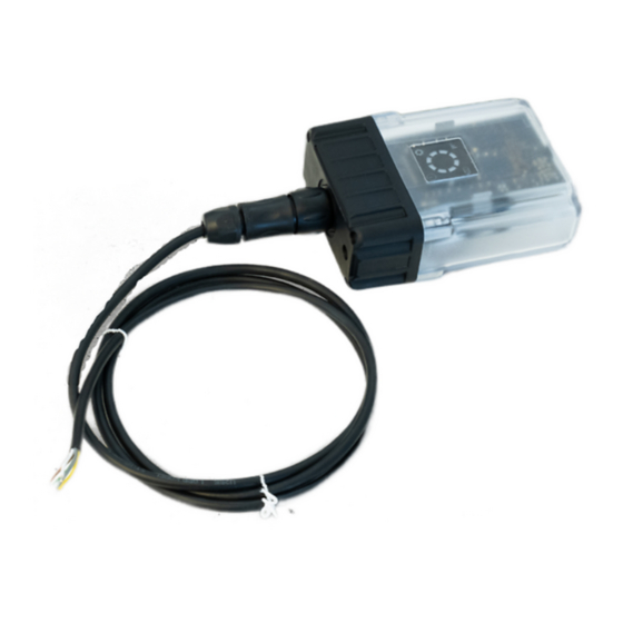
Page 41: Electrical Installation
Run all data cables so that they do not pose a trip hazard and ensure that cables do not have any sharp bends. Data cables must not exceed a lenght of 30m. myDatalogMINIamr with connected Connection cable for Sensor connector on the myDatalogMINIamr myDatalogMINI 1,5 m 1 Sensor connector (7-pin MIL connector) 2 Connection cable for myDatalogMINI 1,5 m... - Page 42 Sensor connector Sensor connector (7- Connection cable for Signal pin MIL connector) myDatalogMINI 1,5 m White Input 3 Gray Input 4 Sensor connector Yellow Input 2 Green Input 1 Brown Ground Connection cable for myDatalogMINI 1,5 m 1. Activate the according mode in the configuration section "measurement channels". The mode is depending on whether you want to connect a meter or a digital contact with the input (see "Measurement channels"...
-
Page 43: Technical Details About The Inputs
"state of the mobile network connection" should then start flickering to indicate the connection establishment (see "Display" on page 52. Note: If the myDatalogMINIamr has still been in transport mode, the transport lock is deactivated by the initiation of the Aloha transmission mode and the device resumes operation according to the configuration settings. -
Page 44: Inputs In "Digital" Mode
The following conditions must be observed for the pulses to be detected correctly: < 1,2 V High > 1,9 V Pulse length >1 ms 7.3.2.1 Inputs in "digital" mode The signal at the input is checked once per second so that the system can react to level changes as quickly as possible. -
Page 45: Chapter 8 Initial Start-Up
Study the manual thoroughly before placing into operation to prevent faulty or incorrect configuration. Utilise the manual to familiarise yourself with the operation of the myDatalogMINIamr and the input screens of the myDatanet server before you begin with the configuration. -
Page 46: Commissioning The System
8.4 Commissioning the system Note: It is recommended that the myDatalogMINIamr is first placed into operation in the office before mounting the device permanently at the place of use. During this process, you should create a site for the later operation on the myDatanet server (see "Creating the site"... - Page 47 How-To-Video: Setting the meter readings 7. If you intend to install the myDatalogMINIamr in a manhole, please ensure that the device can establish a mobile radio connection in its final mouning position with the manhole cover closed before leafing the installation site.
-
Page 48: Testing Communication With The Device
8.5 Testing communication with the device 1. Within the desired customer, create a new site/application based on the IoT application "myDatalogMINIamr " for operation of the myDatalogMINIamr on the myDatanet server (see "Creating the site" on page 79). 2. Configure the created site/application according to your requirements (see "Site configuration" on page 56). - Page 49 Chapter 8 Initial Start-Up 8. Check the data coming in in the Aloha data window of the myDatanet servers, which you can access by clicking on the speech bubble entitled "Aloha" (see "myDatanet Server Manual " 805002). You should pay particular attention to the measurement value "RSSI" (mobile radio signal strength). Note: Additional explanation on the assessment of the "Mobile radio field strength": "RSSI"...
-
Page 51: Chapter 9 User Interfaces
Chapter 9 User interfaces Chapter 9 User interfaces The configuration of the myDatalogMINIamr is carried out via the web interface on the myDatanet server (see "User interface on the myDatanet server" on page 56), which your responsible sales partner will provide to you. -
Page 52: Reed Switch
The MDN Magnet (206.803) included in the scope of delivery is required for operating the reed switch. The reed switch can be used to initiate Aloha mode, to switch on the display of the myDatalogMINIamr for 30 sec. or to switch between the tabs on the screen (error codes and current operating state) if the display is switched... - Page 53 Chapter 9 User interfaces light up in green. The display is activated by briefly pressing the solenoid switch (approx. 1 sec.) (see "Reed switch" on page 52). The display then remains active for 30 sec. , showing subsequently the error codes (provided no active errors have occured) and the current operating state. Using the solenoid switch you can disable automatic switching between the tabs and switch manually between the display screens (see "Reed switch"...
- Page 54 Note: Additional explanation on the assessment of the mobile radio signal strength: "RSSI" > -69 dBm -70...-99 dBm -100...-109 dBm -110...-124 dBm -125...-200 dBm Rev. 01...
- Page 55 Chapter 9 User interfaces The following table contains an overview of the display indications resulting from the previous explanation of the individual symbols:: Display Explanation Transport mode activated (state upon delivery) Reed switch activated Operation according to configuration; no active connection to the server Aloha mode active During connection establishment the symbol for the "status...
-
Page 56: Error Codes
"Procedure in case of connection aborts" on page 28) take place but a normal connection is established instead of an Aloha connection. I.e. the myDatalogMINIamr only connects briefly to the server. In doing so, the measurement data recorded since the last connection establishment is transferred and possible configuration changes are adapted. -
Page 57: Basic
Note: It makes little difference to the power consumption whether the contact is closed or open in the idle state, as the myDatalogMINIamr only applies voltage to the contact for 1 ms every second to check its switching status. The maximum current consumption per switching contact is 317 µA . - Page 58 Mode "Cnt.Inf." 5 Metered measurand of a pulse in the "Imp. unit" 6 String that is used as measurement unit for "Amount per record" by all of the server display elements [0-8 characters]. This has no direct influence on the values. 7 Factor by which the count value of a pulse is multiplied in order to convert from the "Impulse unit"...
-
Page 59: Meter Reading
Chapter 9 User interfaces 9.2.1.1.1.2 Meter Reading "Measurement channels" configuration section, "Meter Reading" tab Mode "Digital" - This tab contains no parameters for inputs operated in "Digital" mode. Mode "Cnt.Inf." 1 Input field to edit the counter reading 2 Button for accepting the new counter reading. This button can only be operated if Aloha mode is active. 3 Response whether or not setting the meter reading was successful. -
Page 60: Configuration
9.2.1.1.1.3 Configuration "Measurement channels" configuration section, "Configuration" tab Mode "Digital" - This tab contains no parameters for inputs operated in "Digital" mode. Mode "Cnt.Inf." 1 Defines the upper scale end of the pointer instruments 2 Number of decimal places that are used by all of the server display elements Rev. -
Page 61: Alarms
Chapter 9 User interfaces 9.2.1.1.1.4 Alarms "Measurement channels" configuration section, "Alarms" tab Mode "Digital" 1 Type of contact connected to the input which is selected in the "Basic" tab (read only) Opening The contact is closed in the idle state (i.e. current is flowing). When actuated, the contact contact (NCC) opens. -
Page 62: Internal Channels
RSSI Mobile radio signal strength Battery Internal battery voltage of the myDatalogMINIamr 2 String that is used as measurement unit by all of the server display elements 3 Buttons to switch between the individual tabs of the configuration section 9.2.1.1.2.2 Alarms "Internal channels"... -
Page 63: Basic
Chapter 9 User interfaces 9.2.1.1.3.1 Basic "Calculated channels" configuration section, "Basic" tab 1 Freely selectable channel title for the calculated channels [0-16 characters] 2 Possible calculation modes for the calculated channels Calculated channel deactivated Table Determines the value for the calculated channel by searching for the row corresponding to the value of a measurement channel in the reference point table. -
Page 64: Calculation
9.2.1.1.3.2 Calculation "Calculated channels" configuration section, "Calculation" tab "Table" calculation mode 1 Selection of the channel from which the input data is used 2 Opens the screen for entering the reference point table (the table rows are interpolated linearly, values outside of the defined table are extrapolated linearly.) "Digital"... -
Page 65: Alarms
Chapter 9 User interfaces 9.2.1.1.3.3 Alarms Note: The evaluation of the alarm thresholds for calculated channels can only occur if the device has transferred the measurement data to the myDatanet server. "Calculated channels" configuration section, "Alarms" tab 1 An alarm is triggered, if the measurement value drops to or below this value. 2 An alarm is triggered, if the measurement value meets or exceeds this value. -
Page 66: Default Input Screen For Configuring The Site
9.2.1.2 Default input screen for configuring the site 9.2.1.2.1 Site Customer Specifies to which customer the site is assigned symbol Assign site to another customer Name Site designation (not relevant for the device or data assignment) [2-50 characters] Device S/N Serial number of the device that is linked to the site (device assignment!) Application Name of the IoT application based on which the site was created Application version... -
Page 67: Alarm Settings
Chapter 9 User interfaces 9.2.1.2.3 Alarm settings Acknowledgement Standard The global server setting is used to determine whether alarms must be acknowledged automatically or manually. automatic Alarms are acknowledged automatically as soon as all of the messages have been sent. If SMS that have a tariff with a delivery confirmation function have also been sent, acknowledgement is provided after delivery confirmation. -
Page 68: Basic
9.2.1.2.4.1 Basic Title 1-5 Freely selectable channel title for the calculated channels [0-16 characters] Mode Possible calculation modes for the calculated channels Calculated channel deactivated Table Defines the lower scale end of the pointer instruments Defines the upper scale end of the pointer instruments Unit String that is used as a measurement unit by all of the server display elements [0-16 characters]. -
Page 69: Calculation
Chapter 9 User interfaces 9.2.1.2.4.2 Calculation Calculated channel deactivated Table Source Selection of the channel from which the input data is used Opens the screen for entering the reference point table (the table rows are interpolated linearly, values outside of the defined table are extrapolated linearly.) Digital Source... -
Page 70: Alarms
Note: Additional explanation: Delta mode Assumption: The source channel contains the counter reading of an infinite counter in m . The calculated channel 1 should contain the flow rate in m /s and calculated channel 2 should contain the flow rate in l/h. Required configuration Parameter Value channel 1... -
Page 71: Basic Settings
Chapter 9 User interfaces 9.2.1.2.5 Basic settings Time zone Regional settings (not relevant for raw measurement data as this is stored in UTC) Daylight saving time Configuration for automatic time adjustment Standard The configuration for the time adjustment is adopted by the global server setting. -
Page 72: Ftp Export Settings
9.2.1.2.6 FTP export settings Note: This configuration section is only visible if the "FTP Agent Extended" licence for the myDatanet server has been enabled. FTP export profile off FTP export deactivated "Name of an List with the FTP export profiles that were created on the myDatanet FTP export server (for creating an FTP export profile, see "myDatanet Server profile"... - Page 73 Even firmware versions that have not successfully undergone all of the internal tests are installed (malfunctions may occur). Identification String specifying the hardware platform implemented in the device and the corresponding hardware version (i.e. the rapidM2M module identification). Prod. rev. Product rev. of the myDatalogMINIamr Rev. 01...
-
Page 74: Gprs
9.2.2.3 GPRS SIM tariff Selected SIM tariff 9.2.2.4 Features Features List of activated chargeable features. Rev. 01... -
Page 75: Chapter 10 Mydatanet Server
Chapter 10 myDatanet server Chapter 10 myDatanet server Note: All of the screenshots show version 50v007 of the myDatanet server using the standard colour scheme. Newer versions may include minor changes to the appearance of the server. 10.1 Overview Overview of the myDatanet server 1 Freely selectable logo 5 Opens the screen to input the global settings for the server... -
Page 76: Customer" Area
10.2 "Customer" area Overview of the "Customer" area 1 Area where an image file can be displayed as a "Map" and/or the OpenStreetMaps map can be displayed The sites can be manually placed on the image file used as a "map". In the OpenStreetMaps map, the sites are only displayed once GPS coordinates have been assigned to the site. - Page 77 Chapter 10 myDatanet server 3 List of tags that are assigned to at least one of the customers displayed in the list of customers. If the list of customers was limited by the search field or selection of a tag, this is taken into consideration when creating the list of tags.
-
Page 78: Sites / Applications" Area At Customer Level
10.3 "Sites / Applications" area at customer level Overview of the "Sites / Applications" area at customer level 1 Area where an image file can be displayed as a "Map" and/or the OpenStreetMaps map can be displayed The sites can be manually placed on the image file used as a "map". In the OpenStreetMaps map, the sites are only displayed once GPS coordinates have been assigned to the site. -
Page 79: Reports
Chapter 10 myDatanet server 2 List of reports (see "Reports" on page 79) 3 List of sites/applications (see "Site" on page 66) 4 Symbol that represents a site on the "Map" 5 Symbol via which a OpenStreetMaps map, on which the sites are displayed, can be loaded. (see "Map view"... - Page 80 2. Click on the "Customer" menu item of the myDatanet server to call up the list of available customers. Select an existing customer or create a new customer. Selecting the customer 1 Menu item to call up the list of customers 3 List of available customers 2 Creating a new customer 3.
- Page 81 Chapter 10 myDatanet server 4. If necessary, change the suggested name of the site, select the desired site type or the desired application from the drop-down list and then click the "Add" button. Completing site creation 1 Name of the site (freely selectable) 3 "Add"...
-
Page 83: Chapter 11 Api
Chapter 11 API Chapter 11 API Important note: The relevant licences are required on the myDatanet server to use the API (Application Programming Interface). For future information contact your responsible sales partner. 11.1 Backend API The API is provided to export data from and import data to the myDatanet server. However, this is not just limited to the pure measurement data but includes all of the data provided by myDatanet server (e.g. -
Page 84: Overview
11.2.1 Overview rapidM2M Playground 1 Input field for the user name 2 Input field for the password 3 List of the available HTTP commands. The HTTP commands are grouped according to their fields of application. 4 Depending on the selected HTTP command, the drop down lists for selecting the customer, user and site that should replace the corresponding wild cards ("$CID"...customer , "$UID"...user, "$SID"...site) in the resource path of the HTTP command are displayed. -
Page 85: Chapter 12 Maintenance
Check all of the connections for leaks or corrosion on a regular basis. Check all of the cables for mechanical damage at regular intervals. Clean the myDatalogMINIamr with a soft, moist cloth. Use a mild cleaning agent, if necessary. 12.2 Replacing the battery The batteries must only be replaced by the manufacturer (see "Contact information"... -
Page 87: Chapter 13 Removal/Disposal
Logo of the EU WEEE Directive This symbol indicates that the requirements of Directive 2012/19/EU regarding the scrap disposal of waste from electric and electronic equipment must be observed. Microtronics Engineering GmbH supports and promotes recycling and environmentally friendly, separate collection/disposal of waste from electric and electronic equipment in order to protect the environment and human health. -
Page 89: Chapter 14 Troubleshooting And Repair
Chapter 14 Troubleshooting and repair Chapter 14 Troubleshooting and repair 14.1 General problems Problem Cause/solution Device does not Battery pack is completely discharged. The batteries must only be replaced by respond (all display the manufacturer (see "Contact information" on page 107) or a certified service LEDs always off). - Page 90 Problem Cause/solution Alarm state was not Check whether the "contact type" (i.e. "opener") and the selection for "warning" detected. or "alarm" (i.e. "when closing") have been chosen according to the installation situation. (digital contact) Alarm state was not Check the alarm settings of the measurement channel. The connection was aborted during the transmission, which is indicated by a transferred although time-out entry in the connection list (see "myDatanet Server Manual "...
-
Page 91: App Log Entries
Chapter 14 Troubleshooting and repair 14.2 App log entries The app log is opened via the context menu, which is displayed by clicking on the three-dot symbol in the list of sites. Code Plain text Description amr.ok Stuck resolved on The meter output connected to input <#>... -
Page 92: Log Entries And Error Codes
14.3 Log entries and error codes Log entry Parameter Description Code Plain text Code Plain text 1000 POWER ON Restart following a power failure Watchdog reset (e.g. because of an exception) Reset was initiated by the device itself (e.g. in event of firmware update) Restart for another reason. - Page 93 Chapter 14 Troubleshooting and repair Log entry Parameter Description Code Plain text Code Plain text 1039 UV MODEM The rechargeable battery or battery voltage once RECOVER again suffices to guarantee a stable connection. This is achieved by replacing the rechargeable battery or battery pack.
- Page 94 Log entry Parameter Description Code Plain text Code Plain text 1201 MODEM NOT Internal error FOUND Contact the manufacturer if the device log includes this error several times (see "Contact information" on page 107). 1202 MODEM CMME The GPRS modem indicates a +CME error. The ERROR parameter specifies the type of error.
- Page 95 Chapter 14 Troubleshooting and repair Log entry Parameter Description Code Plain text Code Plain text 1219 LTE NETWORK NOT REGISTERED Not registered, modem is currently not looking REGISTRATION for any new operators to register HOME Registered, home network SEARCHING Not registered, but the modem is currently looking for a new operator with which it can register DENIED...
- Page 96 Log entry Parameter Description Code Plain text Code Plain text 1335 LOG_SHT2X_ SHT2X SENSOR The internal temperature and air humidity sensor STATE is returning valid values again SHT2X RH ERROR A communication error occured when reading the air humidity value from the internal temperature and air humidity sensor.
-
Page 97: Modem Error
Chapter 14 Troubleshooting and repair Log entry Parameter Description Code Plain text Code Plain text 1910 ACCU 0 E2PROM Rechargeable battery not available ERROR Invalid length of the data structure in the EEPROM of the rechargeable battery No charging profile available in the EEPROM (only with Li-ion rechargeable batteries) Error when reading the SoC-value Error when writing the SoC-value... - Page 98 Log entry Parameter Description Code Plain text Code Plain text 1200 NETLOCK ERROR -966 Error when selecting the network. Check whether the device is in the coverage area. TCP channel error 1200 CHANNEL -965 --- An attempt is being made to write to/read a TCP ABORTED client that is no longer available.
-
Page 99: Evaluating The Device Log
Chapter 14 Troubleshooting and repair 14.4 Evaluating the device log 14.4.1 Evaluating the device log on the myDatanet server The last 300 log entries on the myDatanet server can be called up via the button shown below that is located in the measurement device list. -
Page 101: Chapter 15 Spare Parts And Accessories
Chapter 15 Spare parts and accessories Chapter 15 Spare parts and accessories 15.1 Assembly sets Description Quantity Order number Niro shackle 206.325 Anchor clamp 5,5 - 10,5mm 301017 Gateway MDN Protection casing 300662 Wall bracket for myDatalogMINI 301435 Pipe holder for myDatalogMINI 301437 recommended when using the Gateway MDN Protection casing cannot be used in connection with the Gateway MDN Protection casing... - Page 103 Chapter 16 Document history Chapter 16 Document history Rev. Date Changes 29.04.2024 First version Rev. 01...
- Page 105 Chapter 17 Glossary Chapter 17 Glossary Aloha Connection mode that is specially designed for commissioning. The device maintains a connection to the server for a configurable amount of time and takes a measurement every 3 seconds. During this process, only the internal measurement values (GSM level, voltages, etc.) and the values from the universal inputs (if available) are generated.
- Page 106 Product revision Specifies the revision of the product. The revision is increased every time the product is modified (i.e. electronic system, mechanics, etc.) and is marked on the type plate of the product. rapidM2M Store Is responsible for distributing the app models to the individual myDatanet servers. When installing and updating IoT apps the myDatanet server access the app models provided in the rapidM2M Store .
- Page 107 Chapter 18 Contact information Chapter 18 Contact information Support & Service: Microtronics Engineering GmbH Hauptstrasse 7 3244 Ruprechtshofen Austria, Europe Tel. +43 (0)2756 7718023 support@microtronics.com www.microtronics.com Microtronics Engineering GmbH (Headquarters) Hauptstrasse 7 3244 Ruprechtshofen Austria, Europe Tel. +43 (0)2756 77180 Fax.
- Page 108 Certified by TÜV AUSTRIA: EN ISO 9001:2015, EN ISO 14001:2015, ISO/IEC 27001:2013, EN ISO 50001:2011 for myDatanet | TÜV SÜD: ATEX Directive 2014/34/EU © Microtronics Engineering GmbH. All rights reserved. Photos: Microtronics, shutterstock.com Microtronics Engineering GmbH | www.microtronics.com Hauptstrasse 7 | 3244 Ruprechtshofen | Austria | +43 2756 77180 | office@microtronics.com 301604 | Rev.01...
Need help?
Do you have a question about the myDatalogMINIamr and is the answer not in the manual?
Questions and answers