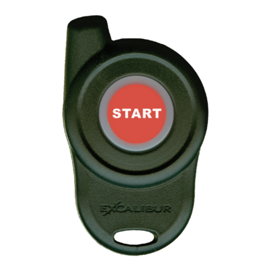
Summary of Contents for Excalibur RS-240-DP
- Page 1 RS-240-DP Keyless Entry & Remote Start Installation Guide June 29, 2011 Temporary cover. Color cover is in a separate file.
-
Page 2: Table Of Contents
Table Of Contents Installation Considerations �������������������������������������������������������������������� 3 6 Pin Main Wire Harness ������������������������������������������������������������������������� 3 Red & Red/White Wires - Constant Power (+) Input ����������������������������� 3 Pink Wire - Ignition #1 (+) Input/Output ������������������������������������������������� 3 Orange Wire - Accessory (+) Output ����������������������������������������������������� 4 Violet Wire - Start (+) Output �����������������������������������������������������������������... -
Page 3: Installation Considerations
Installation Considerations BEFORE STARTING THE INSTALLATION, READ THIS ENTIRE MANUAL TO DETERMINE INSTALLATION REQUIREMENTS • VERIFY EACH CIRCUIT WITH A DIGITAL MULTIMETER • IDENTIFY REQUIRED CIRCUITS FOR THE VEHICLE IN QUESTION • MOUNT ANY SYSTEM COMPONENTS AND ROUTE WIRING AWAY FROM MOVING PARTS OR PARTS OF THE VEHICLE THAT GENERATE EXCESSIVE HEAT •... -
Page 4: Orange Wire - Accessory (+) Output
6 Pin Main Wire Harness (cont’d) ORANGE WIRE - ACCESSORY (+) OUTPUT This circuit is designed to drive accessory circuits like climate control, etc�� It turns on when remote start is activated (slightly earlier than the primary ignition out- put) and turns off only during engine cranking� It will turn back on for the remainder of the remote start sequence. -
Page 5: Black/White Wire - Neutral Safety (-) Input
12 PIN / 10 Wire Secondary Harness (cont’d) BLACK/WHITE WIRE - NEUTRAL SAFETY (-) INPUT REQUIRED� This input is a critical safety circuit which allows remote start operation whenever the gear selector is in park or neutral (automatic transmission)� Remote start will not operate unless this wire sees chassis ground� CONNECTION: Connect this to the neutral safety switch wire that shows (-) ground when the gear selector is in the park and neutral positions�... - Page 6 Wiring Overview Valet Switch Window-mount Receiver Module Adhesive #1 Screw Mounting Disc WIRE LEGEND Hard wire connection required Supported via DATA port 12 PIN HARNESS Flashing Light (-) Output - WHITE/BLACK OEM Alarm Arm (-) Output - GREEN/RED Unlock (-) Output - BLUE System Ground (-) Input - BLACK OEM Alarm Disarm (-) Output - GREEN/BLACK Hood Trigger (-) Input - GRAY...
-
Page 7: Wiring Overview
3 PIN SAT� RELAY PORT (RED) Start (-) Programmable Output - GREEN Constant 12v (+) Output - RED Status (-) Programmable Output - BLUE Green Data Port 6 PIN POWER HARNESS Accessory (+) Output - ORANGE Ignition #1 (+) Input/Output - PINK Start (+) Output - VIOLET Constant 12v (+) Input - RED 30 AMP... -
Page 8: Pin / 10 Wire Secondary Harness (Cont'd)
12 PIN / 10 Wire Secondary Harness (cont’d) LT� GREEN/RED WIRE - OEM ALARM ARM (-) OUTPUT This output provides a 250mA negative pulse when remote start is turned off and when the system’s alarm is armed� CONNECTION: Connect this wire to the vehicle’s OEM alarm arm circuit� Typically, it will show ground when the door cylinder key is turned to the lock position�... -
Page 9: Pin Satellite Relay Port (Red)
3 Pin Satellite Relay Port (RED) GREEN WIRE - START (-) PROGRAMMABLE OUTPUT This output provides a 250mA negative pulse when the large VIOLET start wire is active� It can also be programmed for PULSE AFTER START, STATUS, or DOME- LIGHT SUPERVISION�... -
Page 10: Window Mount Antenna Module
Window Mount Antenna Module This system is equipped with an outboard receiver module. It is designed to be window mounted high on the windshield for optimal performance and range� It is best to mount this module using the double sided stick pad included (be sure to clean glass before adhering)�... -
Page 11: Programmable Features
Programmable Features A matrix of all programmable features and their options are below� For detailed in- formation on each feature, please refer to the operation manual� Use the procedure below to make any necessary changes� Step 1 Turn the ignition key “ON”, then “OFF” Step 2 Within 5 seconds of step 1, press the valet switch 5 times to access user features (10 times to access installer features)�... - Page 12 Back Cover Color cover is in a separate file.


Need help?
Do you have a question about the RS-240-DP and is the answer not in the manual?
Questions and answers