Table of Contents
Advertisement
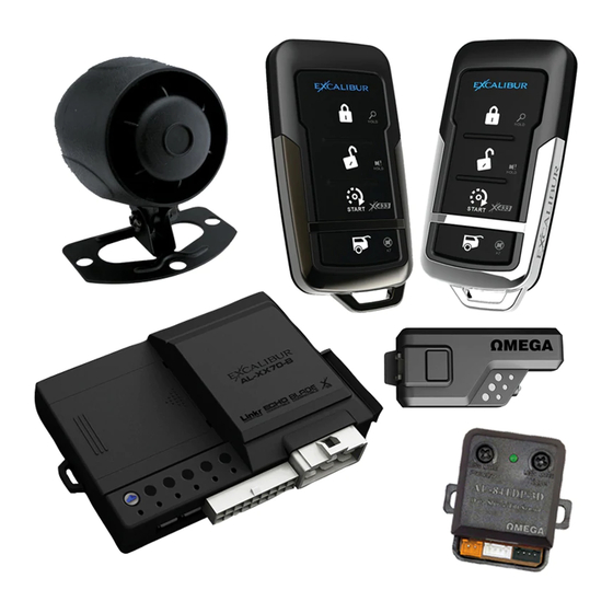
REMOTE START & SECURITY PERFECTED
AL-XX70-B
Quick Reference - Installation Overview
Choose a discreet mounting location for the module and locations
1
for any accessories (siren, sensors, interface module, etc�)� Do not
mount the module yet
Identify vehicle connection points and plan harness routing from
your mounting location� Avoid any moving vehicle parts or parts that
2
generate heat� Also avoid any sharp metal edges� See wiring details
on pages 3-10�
Cut system wires to length, prep your harnesses, and make all wire
connections to the vehicle�
3
NOTE: DATA/MUX WIRES ARE SENSITIVE and MUST BE SPLICED DIRECTLY�
QUICK TAPS ARE NOT RECOMMENDED�
If you are using either of the system's data ports for accessories
4
or modules using DBI protocol, connect these modules now and
confi gure them for DATA MODE.
Perform VEHICLE LEARN (see pages 9 and 12 for instructions)�
This automatically matches the IGN/ACC/START outputs to the vehicle's ignition switch,
5
auto-detects data protocols, chooses the best engine detection method, decides whether
neutral safety circuit is required, and allows you to quickly set engine and transmission
types� FASTER THAN PROGRAMMING!
6
Test the system for all functions.
7
Secure the module(s) and harnesses to the vehicle�
8
Reassemble the vehicle.
9
Test the system for all functions again
WIRE DIAGRAM: CENTER OF THIS BOOKLET
FEATURE CHART: INSIDE BACK COVER
INSTALLATION GUIDE
(you might anger the install gods)
�
(keep the install gods happy)
�
Advertisement
Table of Contents

Related Manuals for Excalibur AL-XX70-B


Summary of Contents for Excalibur AL-XX70-B
- Page 1 REMOTE START & SECURITY PERFECTED AL-XX70-B INSTALLATION GUIDE Quick Reference - Installation Overview Choose a discreet mounting location for the module and locations for any accessories (siren, sensors, interface module, etc�)� Do not mount the module yet � (you might anger the install gods) Identify vehicle connection points and plan harness routing from your mounting location�...
-
Page 2: Table Of Contents
Table Of Contents 6 Pin Main Wire Harness �������������������������������������������������������������������������������������������� 3 Red and Red/White Wires - Constant Power (+) Input ��������������������������������������������� 3 Pink Wire - IGNITION/ACC/START (+) Input/Output ������������������������������������������������ 3 Orange Wire - ACCESSORY/IGN/START (+) Input/Output ������������������������������������� 4 Violet Wire - Start (+) Input/Output ��������������������������������������������������������������������������� 4 Pink/White Wire - IGNITION/ACC/START (+) Input/Output �������������������������������������... -
Page 3: Pin Main Wire Harness
Installation Considerations BEFORE STARTING THE INSTALLATION, READ THIS ENTIRE MANUAL TO FAMILIARIZE YOURSELF WITH ANY INSTALL REQUIREMENTS • BE SURE TO VERIFY EACH CIRCUIT WITH A DIGITAL MULTIMETER • IDENTIFY WHICH CIRCUITS ARE REQUIRED FOR THE VEHICLE IN QUESTION • MOUNT ANY SYSTEM COMPONENTS & ROUTE WIRING AWAY FROM MOVING PARTS OR PARTS OF THE VEHICLE THAT GENERATE EXCESSIVE HEAT •... -
Page 4: Orange Wire - Accessory/Ign/Start (+) Input/Output
6 Pin Main Wire Harness (cont’d) ORANGE WIRE - ACCESSORY/IGN/START (+) INPUT/OUTPUT This circuit is designed to power additional IGNITION, ACCESSORY, or START circuits. By default, it functions as an ACCESSORY output & turns on when remote start is activated (slightly earlier than the ignition output), turns off during engine cranking, &... -
Page 5: Violet/White Wire - Tach Signal Input
18 Pin Secondary Wire Harness (cont’d) CONNECTION (Manual Transmission): When installer feature #11 is ON, connect this to the parking brake switch wire that shows (-) ground when the parking brake is engaged� VIOLET/WHITE WIRE - TACH SIGNAL INPUT This input monitors the engine’s RPM signal. To use the tach wire, perform VEHICLE LEARN (p.12) to auto-program. -
Page 6: Red/White Wire - Trunk Release / 2Nd Channel (-) Output
18 Pin Secondary Wire Harness (cont’d) RED/WHITE WIRE - TRUNK RELEASE / 2ND CHANNEL (-) OUTPUT This output provides a 250mA negative output when the trunk release/CH2 function is activated by the controller. The output will remain as long as the controller button(s) is held. CONNECTION: Connect this wire to the vehicle’s existing trunk release switch if it is a low current negative circuit�... -
Page 7: Pin Secondary Wire Harness
4 Pin Secondary Wire Harness PINK WIRE - 3RD CHANNEL (-) OUTPUT This output provides a 250mA negative output when the CH3 function is activated by the controller. The output will remain as long as the controller button is held. CONNECTION: Connect this wire to any desired add-on accessory that can utilize a negative activation input�... -
Page 8: Wiring Overview Diagram
Wiring Overview Diagram 4 PIN ANALOG SENSOR PORTS Constant 12v (+) Out - RED Ground (-) Out - BLACK BLADE CARTRIDGE SLOT (REMOVE DOOR) Trigger (-) In - BLUE Pre-warn (-) In - GREEN TEMPERATURE SENSOR 18 PIN HARNESS Door Trigger (-) In - GREEN Tach In - VIOLET/WHITE Door Trigger (+) In - VIOLET Light Relay Pin 87 (+/-) In - BLACK/RED... - Page 9 4 PIN DOOR LOCK PORT Lock (-) Out - GREEN Constant 12v (+) Out - PIN Unlock #1 (-) Out - BLUE Unlock #2 (-) Out - PINK 3 PIN SAT� RELAY PORT (RED) Start (-) Out - GREEN Constant 12v (+) Out - RED Ignition (-) Out - BLUE 3 PIN SAT�...
-
Page 10: Pin Satellite Relay Port (Blue)
3 Pin Satellite Relay Port (BLUE) NOTE: There is no dedicated harness included. Use the RED 3-pin harness for this port. GREEN WIRE - ACCESSORY/IGN/START (-) OUTPUT This provides a 250mA negative output when the large ORANGE wire is active. CONNECTION: Connect this directly to the vehicle’s low current negative ACCESSORY/IGN/ START circuit. -
Page 11: Green Data Port
Green Data Port This port provides a direct digital interface for any interface module, or other accessories, using either the DBI protocol or iDatalink protocol� It eliminates the need for several wire-to-wire connections. Refer to the wire diagram overview on page 8 to see which circuits are supported by this port &... -
Page 12: Window Mount Antenna Module
Window Mount Antenna Module This system is equipped with an outboard receiver or transceiver (2-way) module. It is designed to be window mounted high on the windshield for optimal performance & range. It is best to mount this module using the double sided stick pad included (be sure to clean glass before adhering)� Mount it high in the windshield trying to avoid metal parts of the vehicle as they can create “blind spots”... -
Page 13: Tach Programming
Vehicle Learn Procedure Step 1: Turn the ignition key ON (do not start) Step 2: Activate remote start by the remote, input activation wire, or smartphone control� The system will chirp/flash lights to indicate engine type (Default: 1x = Gasoline). Step 3: Press valet to change engine type, if needed: The system will chirp/flash lights to confirm each selection. -
Page 14: Programmable Features
Programmable Features PROGRAMMING FEATURES A matrix of all programmable features & their options are on the next page. For detailed information on each feature, please refer to the operation manual. Use the procedure below to make any necessary changes� NOTE: You can program features via your computer with Omega Weblink. Visit www.omegaweblink.com for more information. - Page 15 User Feature Programming: Ignition on, off, press valet 5 times Lock + Trunk Lock Button Unlock button Trunk button Start button # Feature Unlock + Start (Brake 1x) (Brake 2x) (Brake 3x) (Brake 4x) (Brake 5x) (Brake 6x) 1 Remote Start Run Time 3 min 10 min 15 min...
- Page 16 IM_AL-XX70-B_6/30/2016...
Need help?
Do you have a question about the AL-XX70-B and is the answer not in the manual?
Questions and answers