
Related Manuals for Harvest TEC 547C


Summary of Contents for Harvest TEC 547C
- Page 1 Installation Manual MODEL 547C 55 Gallon Automatic Preservative Applicators Forage Harvester #010-547C-14-INST 5/22...
- Page 2 (intentionally blank)
-
Page 3: Table Of Contents
Harvest Tec 547C Installation Table of Contents Page Introduction Tools Needed Installation of Applicator 5-29 1. Installation of Tank and Saddle 5-10 4 x 5 4 x 6 5 x 5 5 x 6 2. Mounting Front Pumping Plate Support 3. -
Page 4: Introduction
This applicator is designed to apply Harvest Tec buffered propionic acid. The model 547C base kit includes the following parts: Tank, Frame, Pumps, Hose, Baler Mounted Processor, Touchscreen Display, Moisture Sensors, and Miscellaneous Hardware. -
Page 5: Installation Of Applicator
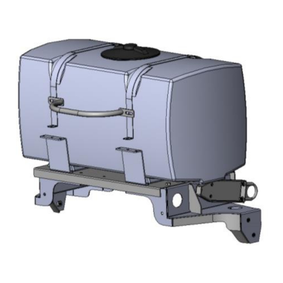
Installation of the Applicator 1. Installation of Tank and Saddle a. Locate the left saddle leg, 001-4703XL, and mount to left side sheet of baler using two ½” x 1-1/2” hex bolts, ½” lock washers, and ½” flat washers. Do not fully tighten. b. - Page 6 001-4402 001-6707HR (x2) (x1) 001-9203SQ 001-4703XAB (x2) 001-4703XA (x2) 001-4703XAX (x2) 001-4703XR (x1) 001-4703XL (x1) **001-4703XAX (x2) are ONLY used on 4x6 models...
- Page 7 4x5 Baler 4x5 Baler Exploded 4x5 Baler...
- Page 8 4x6 Baler 4x6 Baler Exploded 4x6 Baler...
- Page 9 5x5 Baler 5x5 Baler Exploded 5x5 Baler...
- Page 10 5x6 Baler 5x6 Baler Exploded 5x6 Baler...
-
Page 11: Mounting Front Pumping Plate Support
2. Mounting Front Pump Plate Support Figure 1 001-4646C Pump Mounting Plate Holes 4x6 and 5x6 Baler Mounting Holes 001-4703XE 4x5 and 5x5 Baler Mounting Holes Open right side door of baler. Locate mounting holes for your size baler in bracket (001-4703XE). Mount bracket to pre- stamped square holes on diagonal support structure of baler. -
Page 12: Mounting Rear Pump Plate Support
3. Mounting Rear Pump Plate Support Mounting bracket (001-4703XF) will be used to mount the pump mounting bracket to the door support bracket. However each size baler uses a different set of holes in the rear mounting bracket (001-4703XR). Follow the guidance provided below as well as the additional instructions on the next few pages for mounting on your size baler. - Page 13 Mounting Rear Pump Plate Support for 4 X 5 Baler 1. Locate the baler door support bracket. This will be to the left of the Mounting Plate (001-4646C). 2. Use two 3/8” x 1” hex bolts, flat washers, lock washers, and nuts to secure Pump Plate Bracket (001-4703XF) to back side of Pump Mounting Bracket (001-4646C).
- Page 15 Mounting Rear Pump Plate Support for the 4 x 6 Baler 1. Locate the baler door support bracket. This will be to the left of the Mounting Plate (001-4646C). 2. Use two 3/8” x 1” hex bolts, flat washers, lock washers, and nuts to secure Pump Plate Bracket (001-4703XF) to back side of Pump Mounting Bracket (001-4646C).
- Page 17 Mounting Rear Pump Plate Support for the 5 x 5 Baler 1. Locate the baler door support bracket. This will be to the left of the Mounting Plate (001-4646C). 2. Use two 3/8” x 1” hex bolts, flat washers, lock washers, and nuts to secure Pump Plate Bracket (001-4703XF) to back side of Pump Mounting Bracket (001-4646C).
- Page 19 Mounting Rear Pump Plate Support for the 5 x 6 Baler 1. Locate the baler door support bracket. This will be to the left of the Mounting Plate (001-4646C). 2. Use two 3/8” x 1” hex bolts, flat washers, lock washers, and nuts to secure Pump Plate Bracket (001-4703XF) to back side of Pump Mounting Bracket (001-4646C).
-
Page 21: Installation Of Spray Nozzles
4. Installation of the Spray Nozzles a. Locate nozzle block hanger assemblies with tips pre-installed. b. The assembly with the check valves will be mounted to the left hitch support plate when standing next to the PTO just in front and under the large round cross support tube. Use ½”... -
Page 22: Installation Of Drain Fill Kit
5. Installation of Drain Fill Kit Locate parts bag 1. Thread 3/4" elbow fitting (#003-EL3434) into end of tank. Run 3/4" hose from the elbow down the frame to the bottom of the baler. Locate the two holes on the baler’s angled support bracket that line up with the holes in the valve bracket and attach using two 5/16”... -
Page 23: Installation Of Plumbing
6. Installation of Plumbing A. Intake Use the 003-EL3412 on the bottom of the tank to route 1/2” line (002-9001) to the 003-A1212 fitting on the ball valve already attached to the pump plate. Attach hose clamps (003-9003) on both of the fittings. -
Page 24: Installation Of Moisture Sensor Pads And Disks
7. Installation of Moisture Sensor Pads and Disks a. Open rear tail gate of baler and lock in the up position. Refer to baler manual on how to lock door open. b. Remove bale shaping discs on each side of chamber by grinding welds. Once removed grind any remaining welds so sides of bale chamber are smooth. - Page 25 OSR (over-shot rotor) USR (under-shot rotor)
-
Page 26: Installation Of The Controls
8. Installation of Control Use the supplied suction cup mount to position the monitor in the cab. Make sure the glass is clean before installing the suction cup mount. If a non-cabbed tractor is used, use the supplied #10 screws for installation on the fender. -
Page 27: Installation Of The Bale Rate Sensor
9. Installation of Bale Rate Sensor The bale rate timer sensor is used to determine when the baler door is open. With this information the system is able to change the tons/hour automatically (see Operating Instructions, Automatic Mode) and also record information per bale (see Job Records). -
Page 28: Installation Of The Power Cable And Main Wiring Harnesses
The power harness must be connected to the battery! The unit will draw more amps than convenience outlets can handle. Any modifications of the power harness will void systems warranty. CONTACT HARVEST TEC IF MODIFICATION IS REQUIRED! b. This unit will not function on positive ground tractors. -
Page 29: Pin Outs
Wiring Diagrams Pin Outs A. Communication and power harness Pin 1 Can 12 volt Pin 2 Battery 12 volt Pin 3 Orange Keyed power Pin 4 Not Used Pin 5 Yellow Comm channel OL Pin 6 Green Comm channel OH Pin 7 Not used Pin 8... - Page 30 F. End of bale sensor on PIP Pin1 Brown Sensor power Pin2 Blue Sensor ground Pin3 Not used Pin4 Black Signal from sensor G. Moisture and Bale rate sensor connector on PIP Pin 1 Not used Pin 2 Not used Pin 3 Not used Pin 4...
-
Page 31: Parts Breakdowns
Parts Breakdown for the Tank and Saddle Harvest Tec Model 547C Base Kit Ref # Description Part # Ref # Description Part # 55 Gallon tank lid 005-9022H Anchor Bracket 001-4703XA Strap 001-4402 Saddle 001-4703X Tank 005-9203SQ Left Leg 001-4703XL... -
Page 32: Drain Fill Kit
Parts Breakdown for Drain Fill Kit Ref # Description Part # Ref # Description Part # Straight Fitting 003-A3434 Male Coupler 002-2205G Elbow 003-EL3434 Valve Holder 001-6702H Hose Clamps 003-9004 Ball valve 002-2200 Female Coupler 002-2204A Jiffy Clip 008-9010 ¾” Hose 002-9002... -
Page 33: Pump Manifold
Parts Breakdown for Pump Manifold Ref# Description Part# Pump plate 001-4646D Mounting Bracket 001-4646C Pump 007-4120H Street elbow fitting 003-SE38 Nipple fitting 003-M3838 Check valve 002-4566F Elbow fitting 003-EL3812 Tee fitting 003-T3812HB Flow meter assembly 006-4725A Straight fitting 003-A1212 Elbow fitting 003-JEL1238 Filter bowl assembly 002-4315... -
Page 34: Moisture Sensors And Hoses
Parts Breakdown for Moisture Sensor Discs And Hoses Ref# Description Part # CNH RB Moisture Isolator 006-4641FX CNH RB Moisture Disk 006-4641HX ½” JAN Nut ½” Lock ½” D Washer ½” x 4” Carriage Bolt Sensor Bushing 006-4641G Sensor Isolator 006-4641I Moisture Cable 006-4640G3E... -
Page 35: Control Box And Wiring Harnesses
Parts Breakdown for Control Box and Wiring Harnesses Description Part# Power & communication tractor 006-5650T Pump controller harness 006-5650FC Power & communication baler 006-5650RB2 Pump controller 006-5672 Precision Information Processor (PIP) 006-5671RB Terminating resistor 006-5660Z Ram mount 001-2012H Display 006-5670 Bale rate timer 006-7400 Bale rate timer bracket... -
Page 36: Model 547C Installation Kit
Harvest Tec Model 547C Installation Kit 12 11 Ref Description Part # Ref Description Part# Tip –Stainless Pump Plate Bracket 001-4703XF 004-T800067-SS Pump/Valve Mount 001-4703XE Spray Shield Manifold 001-4435NSB Tip –pink Spray Block Holder 001-4703XD 004-T8001-PT Tip –brown Elbow 003-SE14F 004-T80015-PT Tip –red... - Page 37 Harvest Tec, LLC. Warranty and Liability Agreement Harvest Tec, LLC. will repair or replace components that are found to be defective within 12 months from the date of manufacture. Under no circumstances does this warranty cover any components which in the opinion of Harvest Tec, LLC.
- Page 38 HARVEST TEC, LLC. P.O. BOX 63 2821 HARVEY STREET HUDSON, WI 54016 PHONE: 715-386-9100 1-800-635-7468 FAX: 715-381-1792 Email: info@harvesttec.com...
Need help?
Do you have a question about the 547C and is the answer not in the manual?
Questions and answers