Advertisement
Quick Links
Advertisement

Subscribe to Our Youtube Channel
Related Manuals for FRENCH FITNESS X9


Summary of Contents for FRENCH FITNESS X9
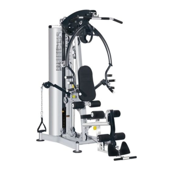
- Page 1 FUNCTIONAL MULTI GYM SYSTEM ASSEMBLY MANUAL...
-
Page 2: Tech Specs
FEATURES • Heavy duty steel construction • Thick pads with extra support and cushioning • Space saving design • Adjustable seat height and back rest to perform various exercises with ease • Reinforced nylon pulleyʼs with precision machined steel ball bearings •... -
Page 3: Parts Diagram
Parts Diagram 12x3 (M12x20) Outer Hexagonal Bolt (M10x20) (M12x70) (Ф10хФ30) Outer Hexagonal Bolt Pulley Spacer (Ф10) Washer Positioning Bolt Outer Hexagonal Bolt 53 ( (Ф12) M12) (M10x60) (M10) (M2) Washer (M12x130) Flat washer Lock Nut Outer Hexagonal Bolt Lock Nut Outer Hexagonal Bolt... - Page 4 Parts Diagram (Ф16x137) (M10x16) (Ф17x123) (M12x75) (M10x85) Outer Hexagonal Bolt Outer Hexagonal Bolt (M10x130) (M10x45) (M10x115) (M8x45) (Ф8) Washer Outer Hexagonal Bolt Outer Hexagonal Bolt Outer Hexagonal Bolt Outer Hexagonal Bolt (M10x110) (M10x70) (M8) Lock Nut Outer Hexagonal Bolt Outer Hexagonal Bolt Adjustment Board Cable166.5"...
- Page 5 I n s t a ll in g S t e p 1 Ex p l o d e d Vie w...
-
Page 6: Installation Instruction
Installation Instruction 1. Put Φ10 washer (49) over M10*20 outer hexagonal bolts (5), and fasten the guiding rod assembly (2) to the under frame weldment (1). 2. Install the cushion (4) on the guiding rod assembly (2). - Page 7 I n s t a l l in g St e p 2 Ex p l o d e d Vie w...
- Page 8 I n s t a l l i n g S t e p 2 A f t e r I n s t a l l a t i o n Installation Instruction Place 11 PCS cast iron counterweight lower piece (7) and cast iron counterweight top piece (6) in sequence on the upper end of the guiding rod assembly (2).
- Page 9 I n s t a l l i n g S t e p 3 E x p l o d e d V i e w...
- Page 10 I n s t a l l i n g S t e p 3 A f t e r I n s t a l l a t i o n Installation Instruction Fasten the inclined support beam (12) to the chassis assembly with M12*70 outer hexagonal bolts (51), Φ12 at washers (52), and M12 lock nuts (53).
- Page 11 I n s t a ll in g St e p 4 Ex p l o d e d Vie w...
- Page 12 Installation Instruction 1. Fix the shield support frame (14) and the upper beam (13) together with M10*60 outer hexagonal bolts (56), Φ10 washers (49) and M10 lock nuts (57). 2. Connect the upper beam (13) and the guiding rod (2) together, and fasten them with M10*20 outer hexagonal bolts (5), Φ10 washers (49) M10 lock nuts (57).
- Page 13 I n s t a l l in g S t e p 5 Ex p l o d e d Vie w...
- Page 14 I n s t a l l i n g S t e p 5 A f t e r I n s t a l l a t i o n Installation Instruction 1. Use M12*130 outer hexagonal bolts (58), Φ12 washers (52) and M12 lock nuts (53) to fasten the decorative boards (15, 16) to the upper beam and the inclined support beam assembly.
- Page 15 I n s t a l l in g St e p 6 Ex p l o d e d Vie w...
- Page 16 I n s t a l l i n g S t e p 6 A f t e r I n s t a l l a t i o n Installation Instruction 1. Use M12*70 outer hexagonal bolts (51), Φ12 washers (52) and M12 lock nuts (53) to fasten the seat support in tube assembly (18) to the lowerhole of the inclined support beam.
- Page 17 I n s t a l l in g St e p 7 Ex p l o d e d Vie w...
- Page 18 I n s t a l l i n g S t e p 7 A f t e r I n s t a l l a t i o n Installation Instruction 1. Use the Φ17*123 front pushing frame shaft (59) to connect the front pushing frame (21) and the decorative boards (15, 16) together, and fasten it to both ends of the front pushing frame shaft (21) with M10*20 outer hexagonal bolts (5) and Φ10*Φ30 washers (3).
- Page 19 I n s t a l l in g St e p 8 Ex p l o d e d Vie w 62 52...
- Page 20 I n s t a l l i n g S t e p 8 A f t e r I n s t a l l a t i o n Installation Instruction 1. Fasten the butter y arm-left (24) to the butter y arm xing board of the inclined support beam with M10*16 outer hexagonal bolts (61) and Φ10*Φ30 washers (3).
- Page 21 I n s t a l l i n g S t e p 9 E x p l o d e d V i e w 66 65 Cable (#29) = 166.5" (1 bolt end and one rubber ball end)
- Page 22 Installing Step 9 Rope Wiring Diagram Cable (#29) = 166.5" (1 bolt end and one rubber ball end)
- Page 23 I n s t a l l i n g S t e p 9 A f t e r I n s t a l l a t i o n high pull steel rope 4240 mm Installation Instruction 1.
- Page 24 I n s t a l l i n g S t e p 1 0 E x p l o d e d V i e w Cable (#67) = 57.5" (1 bolt end and 1 hole end)
- Page 25 I n s t a l l i n g S t e p 1 0 A f t e r I n s t a l l a t i o n Transitional Rope 1380 mm Cable (#67) =57.5" (1 bolt end and 1 hole end) Installation Instruction 1.
- Page 26 I n s t a l l i n g S t e p 1 1 E x p l o d e d V i e w Cable (#68) = 203" (2 rubber ball ends)
- Page 27 I n s t a l l i n g S t e p 1 1 R o p e W r i t i n g D i a g r a m Cable (#68) = 203" (2 rubber ball ends)
- Page 28 I n s t a l l i n g S t e p 1 1 A f t e r I n s t a l l a t i o n Upper Arm Rope 5150 mm Installation Instruction 1.
- Page 29 I n s t a l l i n g S t e p 1 2 E x p l o d e d V i e w...
- Page 30 I n s t a l l i n g S t e p 1 2 A f t e r I n s t a l l a t i o n 3290mm Low Pull Steel Rope Installation Instruction 1.
- Page 31 I n s t a l l i n g S t e p 1 3 R o p e W r i t i n g D i a g r a m...
- Page 32 I n s t a l l i n g S t e p 1 3 E x p l o d e d V i e w Cable (#32) = 130" (1 hole end and one rubber ball end) Installation Instruction 1.
- Page 33 I n s t a l l i n g S t e p 1 4 E x p l o d e d V i e w...
- Page 34 I n s t a l l i n g S t e p 1 4 A f t e r I n s t a l l a t i o n Installation Instruction Fasten the backrest cushion (33) on the backrest adjusting board (35) with M10*20 outer hexagonal bolts (5) and Φ10 washer (49).
- Page 35 I n s t a l l i n g S t e p 1 5 E x p l o d e d V i e w...
- Page 36 I n s t a l l i n g S t e p 1 5 A f t e r I n s t a l l a t i o n Installation Instruction Insert the foam rod (40) into the backrest adjustment frame, and put the foam inner end cap (37), foam (36), and foam outer end cap (38) in sequence at both ends of the foam rod (40).
- Page 37 I n s t a l l i n g S t e p 1 6 E x p l o d e d V i e w 70 73...
- Page 38 I n s t a l l i n g S t e p 1 6 A f t e r I n s t a l l a t i o n Installation Instruction 1. Fasten the shield (42 ) on the shield support frame and the chasis shield fixing piece with M8*16 outer hexagonal bolt (73) and Φ8 washer (70).
- Page 39 I n s t a l l i n g S t e p 1 7 E x p l o d e d V i e w...
- Page 40 I n s t a l l i n g S t e p 1 7 A f t e r I n s t a l l a t i o n Installation Instruction 1. Connect the 9-link chain+quick-connect ring (43) to the pull strap (45), and then connect the other end of the 9-link chain ring (4 2.
Need help?
Do you have a question about the X9 and is the answer not in the manual?
Questions and answers