
Related Manuals for FRENCH FITNESS FFS-HAA


Summary of Contents for FRENCH FITNESS FFS-HAA
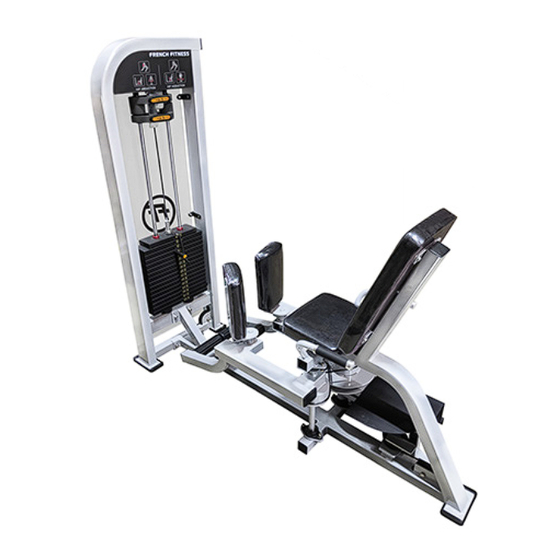
- Page 1 FFS-HAA / FFT-HAA French Fitness Shasta Inner Outer Thigh & Tahoe Hip Abduction / Adduction ASSEMBLY MANUAL...
- Page 2 FEATURES • • 50 x 100 mm, thickness 3mm Steel tube Fiberglass-impregnated nylon pulleys • feature sealed bearings Q235 steel frame ensures maximum • structural integrity Solid-steel weight plates. Top weight • plate is fitted with self-lubricating Each frame receives an electrostatic bushings powder coat finish to ensure maximum adhesion and durability...
-
Page 3: Table Of Contents
TABLE OF CONTENTS PARTS LIST ...................... 4 CLEAN GUIDE RODS ..................5 MAIN FRAME AND SIDE FRAME ASSEMBLY ..........6 SIDE FRAME ASSEMBLY ................. 7 ARM FRAME ASSEMBLY ................8 MAIN FRAME ASSEMBLY ................9 WEIGHT SET ASSEMBLY: 7 STEPS ..............10... -
Page 4: Parts List
P A R T S L I S T ITEM Name QTY. SIDE FRAME BACK CUSHION SEAT CUSHION MAIN FRAME SCREW M12*65 NUT, M12 SCREW, M8*25 SCREW, M8*30 SCREW, M8*70 SCREW, M12*25 BEARING 205 SCREW, M12x20 SCREW, M10x75 SCREW, M6x25 SCREW, M10x80 SCREW, M12x35 BEARING 205... -
Page 5: Clean Guide Rods
C L E A N G U I D E R O D S Step must be completed prior to installing. Failure to do so can leave residue from packaging and other sources stuck in the bushings. Guide rods need to make sure they are cleaned prior to installation otherwise this will cause the top plate to get stuck. -
Page 6: Main Frame And Side Frame Assembly
M A I N F R A M E A N D S I D E F R A M E A S S E M B L Y See 7 Step Weight Stack Assembly Directions, starting on Page 11, for Weight Stack Assembly Details... -
Page 7: Side Frame Assembly
S I D E F R A M E A S S E M B L Y... -
Page 8: Arm Frame Assembly
A R M F R A M E A S S E M B L Y... -
Page 9: Main Frame Assembly
M A I N F R A M E A S S E M B L Y See 7 Step Weight Stack Assembly Directions, starting on Page 11, for Weight Stack Assembly Details ITEM Name QTY. SCREW M12X110 PLACARD SCREW, M8*55 GUIDE ROD 0.91M ASSY,WEIGHT PLATE SCREW, M10*50... -
Page 10: Weight Set Assembly: 7 Steps
W E I G H T S T A C K A S S E M B L Y See 7 Step Weight Stack Assembly Directions, starting on Page 11, for Weight Stack Assembly Details ITEM Name QTY. Top Weight Plate Underside Weight plate Adjustable bolt... - Page 11 W E I G H T S T A C K A S S E M B L Y S T E P 1 . R U B B E R B U M P E R S S T E P 2 . G U I D E R O D S - T I L T O U T...
- Page 12 S T E P 3 . W E I G H T P L A T E S STEP 4. TOP PLATE/SELECTOR ROD- REMOVE FROM CABLE FOR NOW + INSTALL THE TOP PLATE...
- Page 13 S T E P 5 . A D A P T E R W E I G H T S S T E P 6 . T I L T I N G U I D E R O D S - R A I S E T H E M I N O R D E R T O B O L T T H E M I N...
- Page 14 STEP 7. INSTALL THE WEIGHT SELECTOR PIN AND REATTACH CABLE TO THE TOP PLATE AND THEN STORE WEIGHT ADAPTERS ON THE CHROME BRACKET AT THE TOP SO THAT THE CABLE CAN BE TIGHTENED AND ADJUSTED...
- Page 15 A S S E M B L Y I N S T R U C T I O N S 1) Attach the shrouds using included screws to the black brackets 2) Once attached, apply circular "FF" stickers onto the shroud, on the side that faces away from the weight stacks, with the bottom of the FF circle at the height of the top weight stack plate.
Need help?
Do you have a question about the FFS-HAA and is the answer not in the manual?
Questions and answers