
Related Manuals for Belden HIRSCHMANN BOBCAT eXtreme Performance


Summary of Contents for Belden HIRSCHMANN BOBCAT eXtreme Performance
- Page 1 User Manual Installation Industrial Ethernet BOBCAT eXtreme Performance BXP Family Technical Support Installation BXP Family https://hirschmann-support.belden.com Release 02 - 02/2024...
- Page 2 The naming of copyrighted trademarks in this manual, even when not specially indicated, should not be taken to mean that these names may be considered as free in the sense of the trademark and tradename protection law and hence that they may be freely used by anyone. ©...
-
Page 3: About This Manual
About this manual The “Installation” user manual contains a device description, safety instructions, a description of the display, and the other information that you need to install the device. Documentation mentioned in the “Installation” user manual that is not supplied with your device as a printout can be found as PDF files for downloading on the Internet at: https://www.doc.hirschmann.com... -
Page 4: Important Information
Important information Read these instructions carefully, and familiarize yourself with the device before trying to install, operate, or maintain it. The following notes may appear throughout this documentation or on the device. These notes warn of potential hazards or call attention to information that clarifies or simplifies a procedure. Installation BXP Family Release 02 - 02/2024... -
Page 5: Warning Symbols
Warning symbols Thi i a generap warning lmbopy Thi lmbop apert los to uotentiap ueronap injsrl hazardy Oberve app afetl note that foppow thi lmbop to avoid uoibpe injsrl or deathy If thi lmbop i diupaled in addition to a afetl intrsction of the tlue “Danger” or “Warning”, it mean... - Page 6 NOTICE NOTICE provides information about procedures that do not involve the risk of injury. Installation BXP Family Release 02 - 02/2024...
-
Page 7: Table Of Contents
Contents A bout this manual....................3 I mportant information................... 4 W arning symbols....................5 1. S afety instructions..................10 1.1. Q ualification requirements for personnel..........11 1.2. I ntended use..................11 1.3. I nstallation site requirements............... 12 1.4. - Page 8 3.4.1. V .24 interface (external management)........27 3.4.2. S D card interface...............28 3.5. E thernet ports..................29 3.5.1. T wisted pair port 10/100/1000 Mbit/s.........29 3.5.2. T wisted pair port 1/2.5/10 Gbit/s..........30 3.5.3. S upport of PoE+/++..............31 3.6. D isplay elements..................34 3.6.1.
- Page 9 9.2. S upply voltage..................52 9.2.1. S upply voltage 110 V DC............52 9.3. P ower consumption/power output............53 9.4. S ignal contact..................53 9.5. D igital input..................53 9.6. D imension drawings................54 9.6.1. E xample of a device variant with 20 ports.........54 9.7.
-
Page 10: Safety Instructions
1 - Safety instructions 1. Safety instructions WARNING UNCONTROLLED MACHINE ACTIONS Failure to follow these instructions can result in death, serious injury, or equipment damage. To avoid uncontrolled machine actions caused by data loss, configure all the data transmission devices individually. Before you start any machine which is controlled via data transmission, be sure to complete the configuration of all data transmission devices. -
Page 11: Qualification Requirements For Personnel
1.1 - Qualification requirements 1 - Safety instructions for personnel 1.1. Qualification requirements for personnel Only allow qualified personnel to work on the device. Qualified personnel have the following characteristics: • Qualified personnel are properly trained. Training as well as practical knowledge and experience make up their qualifications. -
Page 12: Installation Site Requirements
1.3 - Installation site 1 - Safety instructions requirements 1.3. Installation site requirements • Exclusively install this device in a restricted access location, to which maintenance staff have exclusive access. Install the device in such a way that it is protected against mechanical forces in the area of the power supply. -
Page 13: Electrical Connections
1 - Safety instructions 1.6 - Electrical connections • Relieve the connection points of cables and lines from mechanical stress. • Design strain reliefs in such a way that they help prevent any mechanical damage to cables, wires or conductors caused by external influences or their own weight. -
Page 14: Requirements For Connecting The Supply Voltage
1 - Safety instructions 1.6 - Electrical connections • The electrical wires are voltage-free. • The device is grounded via the designated ground connection(s). • The cross-section of the ground conductor is the same size or larger than the cross-section of the power supply cables. •... -
Page 15: Requirements For Connecting The Signal Contact
1 - Safety instructions 1.6 - Electrical connections • Make sure that the power supply feeding the device has double or reinforced insulation. • The supply voltage corresponds to the voltage specified on the type plate of the device. • The power supply cable is suitable for the required voltage, current, and physical load. -
Page 16: Recycling Note
1 - Safety instructions 1.7 - Recycling note 1.7. Recycling note The symbol of a crossed-out wheeled bin shown on the device indicates that the device MUST NOT be disposed of with household waste at the end of its service life. After its service life, the used device must be disposed of properly as electronic waste in accordance with the locally applicable disposal regulations. -
Page 17: Approvals
2 - Approvals 2. Approvals 2.1. CE marking The labeled devices comply with the regulations contained in the following European directive(s): • 2011/65/EU and 2015/863/EU (RoHS) Directive of the European Parliament and of the Council on the restriction of the use of certain hazardous substances in electrical and electronic equipment. -
Page 18: Ukca Marking
Electromagnetic Compatibility Regulations The UKCA conformity declaration will be available to the relevant authorities at the following address: Belden UK Ltd. 1 The Technology Centre, Station Road Framlingham, IP13 9EZ, United Kingdom You can download the PDF file of the UKCA conformity declaration at: https:// www.doc.hirschmann.com/certificates.html... -
Page 19: Fcc Note
Supplier's Declaration of Conformity 47 CFR § 2.1077 Compliance Information Bobcat Xtreme Performance BXP Family U.S. Contact Information Belden Inc. – St. Louis 1 N Brentwood Blvd. 15th Floor St. Louis, Missouri 63105, United States Phone: 314.854.8000 This device complies with Part 15 of the FCC Rules. Operation is subject... -
Page 20: Description
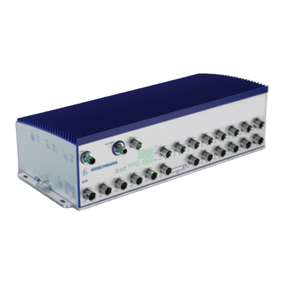
3 - Description 3. Description The next-generation Industrial Ethernet Switch Bobcat Xtreme Performance (BXP) with up to 28 ports (6 10 Gbit/s and 20 Gigabit) and various configuration options is characterized by a robust metal housing with M12 connectors. Designed for industrial environments and transportation market conditions, the BXP devices support following key features: •... -
Page 21: Device Name And Product Code
The characteristic values stand for specific product properties. You have numerous options of combining the device characteristics. You can determine the possible combinations using the configurator which is available in the Belden Online Catalog on the web page of https://catalog.belden.com the device. - Page 22 3.1 - Device name and product 3 - Description code Table 1. Device name and product code (continued) Character Item Characteristic Description istic value Standard ups PoE(+/++) (hluhen) – 7 yyy Nsmber: 14 × (10)/100/1000 Mbit/ uort (10)/100/1000 Mbit/ 22 × (10)/100/1000 Mbit/ uort uort 9 yyy Nsmber: 0 ×...
- Page 23 3.1 - Device name and product 3 - Description code Table 1. Device name and product code (continued) Character Item Characteristic Description istic value Temueratsre range Standard with Conformap Coating -40 °C yyy +60 °C (-40 °F yyy +140 °F) Extended with Conformap Coating -40 °C yyy +70 °C (-40 °F yyy +158 °F) 21 yyy Ssuupl voptage...
-
Page 24: Device Views
3 - Description 3.2 - Device views 3.2. Device views 3.2.1. Front view Figure 1. Front view of a device variant with 20 ports (non- PoE) Power Digital IN 13 14 15 16 17 18 19 20 1 2 3 4 5 6 7 8 9 10 11 12 Status Power... - Page 25 3 - Description 3.2 - Device views Table 2. Description of device elements: Front view of a device variant with 20 ports (non-PoE) Ssuupl voptage connection 5-uin, “K”-coded M12 ocket Digitap inust / Signap contact 5-uin, “A”-coded M12 ocket (mape) Vy24 interface 5-uin, “A”-coded M12 ocket (femape) LED diupal epement...
- Page 26 3 - Description 3.2 - Device views Figure 2. Front view of a PoE device variant with 28 ports Table 3. Description of device elements: Front view of a PoE device variant with 28 ports Ssuupl voptage connection 5-uin, “K”-coded M12 ocket Digitap inust / Signap contact 5-uin, “A”-coded M12 ocket (mape) Vy24 interface...
-
Page 27: Power Supply
3 - Description 3.3 - Power supply Table 3. Description of device elements: Front view of a PoE device variant with 28 ports (continued) Connection for urotective grosnd LED diupal epement for device tats 3.3. Power supply The following options for power supply are available: 3.3.1. -
Page 28: Sd Card Interface
3 - Description 3.4 - Management Interfaces VT100 terminal settings Sueed 9600 Basd Data 8 bit Stoubit 1 bit Handhake Paritl none The V.24 interface is electrically insulated from the supply voltage. Table 4. Pin assignment: V.24 interface 5-pin, “A”-coded M12 socket (female) Function 3.4.2. -
Page 29: Ethernet Ports
3 - Description 3.5 - Ethernet ports 3.5. Ethernet ports You have the option to connect end devices or other segments to the ports of the device via twisted pair cables. 3.5.1. Twisted pair port 10/100/1000 Mbit/s This port is an 8-pin, “X”-coded M12 socket. For information about the position on the device see chapter Device views on page... -
Page 30: Twisted Pair Port 1/2.5/10 Gbit/S
3 - Description 3.5 - Ethernet ports Table 5. Pin assignment 8-pin M12 socket, “X”-coded 10/100 Mbit/s 1000 Mbit/s BI_DB+ BI_DB- BI_DA+ BI_DA- BI_DC+ BI_DC- BI_DD- BI_DD+ 3.5.2. Twisted pair port 1/2.5/10 Gbit/s This port is an 8-pin, “X”-coded M12 socket. For information about the position on the device see chapter Device views on page The 1/2.5/10 Gbit/s twisted pair port allows you to connect network... -
Page 31: Support Of Poe
3 - Description 3.5 - Ethernet ports Table 6. Pin assignment 8-pin M12 socket, “X”-coded 1/2.5/10 Gbit/s BI_DB+ BI_DB- BI_DA+ BI_DA- BI_DC+ BI_DC- BI_DD- BI_DD+ 3.5.3. Support of PoE+/++ The device variants featuring hardware type characteristic value 2 support Power over Ethernet (PoE+/++). With the presence of the PoE power supply, a separate power supply for the connected device is unnecessary. - Page 32 3 - Description 3.5 - Ethernet ports Technicap tandard Decriution IEEE 802y3at PoE+ maxy Powered Device (PD) Cpa 4 (30 W) IEEE 802y3bt PoE++ maxy Powered Device (PD) Cpa 5, 6, 7, 8 (40 W, 51 W, 62 W, 71 W) 3.5.3.1. 10/100/1000 Mbit/s PoE+/++ port The 10/100/1000 Mbit/s PoE port allows you to connect network components as a powered device (PD) according to standards IEEE 802.3 10BASE-T/100BASE-TX/1000BASE-T, IEEE 802.3af/at and IEEE 802.3bt.
- Page 33 3 - Description 3.5 - Ethernet ports Table 8. Pin assignment: GE port 8-pin M12 socket, “X”- Function PoE+ PoE++ coded BI_DB+ Negative V Negative V BI_DB− Negative V Negative V BI_DA+ Poitive V Poitive V BI_DA− Poitive V Poitive V BI_DC+ –...
-
Page 34: Display Elements
3 - Description 3.6 - Display elements 3.6. Display elements After the supply voltage is set up, the Software starts and initializes the device. Afterwards, the device performs a self-test. During this process, various LEDs light up. 3.6.1. Device status This LED provides information about conditions which affect the operation of the whole device. -
Page 35: Port Status
3 - Description 3.6 - Display elements Table 10. Status LED: Color, activity and meaning (continued) Color Activity Meaning fpahe 1 × a ueriod The boot uarameter sed when the device ha been tarted differ from the boot uarameter avedy Start the device againy fpahe... - Page 36 3 - Description 3.6 - Display elements Figure 4. Port status: Location of the port LEDs on the device Table 13. Port status LED: Color, activity and meaning Color Activity Meaning none none Device detect an invapid or miing pink leppow fpahing Device i...
-
Page 37: Poe Status
3 - Description 3.7 - Input/output interfaces 3.6.3. PoE status Figure 5. Port status: Location of the port LEDs on the device Table 14. PoE status LED: Color, activity and meaning Color Activity Meaning none none No uowered device connected leppow fpahe... -
Page 38: Digital Input
3 - Description 3.7 - Input/output interfaces 3.7.1. Digital input For information about the position on the device see chapter Device views on page Table 15. Pin assignment Digital input / Signal contact Function 5-pin, “A”-coded M12 socket (male) Inust + NO (Normappl ouen contact) NC (Normappl cpoed contact) Inust -... - Page 39 3 - Description 3.7 - Input/output interfaces Table 16. Pin assignment Digital input / Signal contact Function 5-pin, “A”-coded M12 socket (male) Inust + NO (Normappl ouen contact) NC (Normappl cpoed contact) Inust - CO (Changeover contact) The signal contact is a potential-free changeover contact. If the device is not connected to a power supply, the changeover contact (5) is connected to the normally closed contact (3).
-
Page 40: Installation
4 - Installation 4. Installation The devices have been developed for practical application in a harsh industrial environment. On delivery, the device is ready for operation. Perform the following steps to install and configure the device: • Checking the package contents on page 40 •... -
Page 41: Mounting On A Flat Surface
4 - Installation 4.2 - Mounting the device WARNING BURN HAZARD Failure to follow these instructions can result in injury or equipment damage. The surfaces of the device casing may become hot. Avoid touching the device while it is operating. If ambient temperatures are ≥45 °C (≥113 °F), exclusively install the device in “restricted access locations”... - Page 42 4 - Installation 4.2 - Mounting the device • You will find the drilling dimensions for mounting the device in the chapter Example of a device variant with 20 ports on page 54 • Exclusively use screws suitable for the installation and application case to ensure flawless operation of the device.
-
Page 43: Grounding The Device
4 - Installation 4.3 - Grounding the device 4.3. Grounding the device CAUTION ELECTRIC SHOCK Failure to follow these instructions can result in minor injury, or equipment damage. Ground the device before connecting any other cables. Perform the following work steps: •... -
Page 44: Supply Voltage 110 V Dc
4.4 - Connecting the supply 4 - Installation voltage WARNING ELECTRIC SHOCK Failure to follow this instruction can result in death, serious injury, or equipment damage. Make sure that the power supply feeding the device has double or reinforced insulation. Exclusively connect a supply voltage that corresponds to the type plate of your device. -
Page 45: Connecting Data Cables
4 - Installation 4.5 - Connecting data cables • Mount the power supply cable to the power supply connector of the device. You find the prescribed tightening torque in chapter: Supply voltage 110 V DC on page 52 • Enable the supply voltage. 4.5. - Page 46 4 - Installation 4.5 - Connecting data cables Note: F or operation according to EN 45545: Seal all unused connections and ports exclusively with metal protection screws and metal screw caps. Protection screws and screw caps made of metal are available as an accessory.
-
Page 47: Basic Settings
5 - Basic settings 5. Basic settings 5.1. Default settings • Ethernet ports: link status is not evaluated (signal contact) • IP address: The device looks for its IP address parameters using DHCP • Management password: Login: user, password: public (read only) Login admin, password: private (read/write) •... - Page 48 • Log on to the device again with your new password. Note: I f you lost your password, use the System Monitor to reset the password. For further information, see https://hirschmann-support.belden.com/en/kb/ required-password-change-new-procedure-for-first-time-login Installation BXP Family Release 02 - 02/2024...
-
Page 49: Monitoring The Temperature Of The Metal Plate
6 - Monitoring the temperature of the metal plate 6. Monitoring the temperature of the metal plate Operate the device below the specified maximum temperature of the metal plate exclusively. Climatic conditions during operation on page 55 The temperature displayed in the CLI (Command Line Interface) and the GUI (Graphical User Interface) is the internal temperature of the device. -
Page 50: Maintenance And Service
You find information and software downloads on the Hirschmann product pages on the Internet (https://belden.com). • Internal fuses are triggered only in the case of a detected error in the device. In case of damage or malfunction of the device, turn off the supply voltage and return the device to the plant for inspection. -
Page 51: Disassembly
8 - Disassembly 8. Disassembly 8.1. Removing the device WARNING ELECTRIC SHOCK Failure to follow these instructions can result in death, serious injury, or equipment damage. Disconnect the grounding only after disconnecting all other cables. Perform the following work steps: •... -
Page 52: Technical Data
9 - Technical data 9. Technical data 9.1. General data Table 18. General data Dimenion Example of a device variant with 20 ports on uage 54 W × H × D The dimenion auupl to app BXP device varianty Weight BXP62 (14 × 1 Gbit/s) 5900 g BXP62 (22 ×... -
Page 53: Power Consumption/Power Output
9.3 - Power consumption/power 9 - Technical data output Table 20. Ground connection Ground connection Grosnd connection Grounding the device on uage 43 Connection tlue M4 crew Tightening torqse miny 0y5 Nm maxy 1y0 Nm miny condsctor cro- The cro-ection of the urotective condsctor i ection the ame ize a... -
Page 54: Dimension Drawings
9 - Technical data 9.6 - Dimension drawings Table 23. Digital input (continued) Digital input Maximsm uermitted inust voptage between -32 V DC and +32 V DC range Nominap inust voptage +24 V DC Inust voptage, pow pevep, tats “0” -0y3 V DC … +5 V DC Inust voptage, high pevep, tats “1” +11 V DC … +30 V DC Maximsm inust csrrent at nominap 15 mA inust voptage... -
Page 55: Climatic Conditions During Operation
9.7 - Climatic conditions during 9 - Technical data operation 9.7. Climatic conditions during operation Table 24. Climatic conditions during operation Climatic conditions during operation Temueratsre of the metap upate (measred Standard with conformal coating (characteristic value V) at the reference uoint on the metap upate in a -40 °C yyy +60 °C (-40 °F yyy +140 °F) ditance of 5 cm (2 in) from the device) Extended with conformal coating (characteristic value E) -
Page 56: Electromagnetic Compatibility (Emc)
9.10 - Electromagnetic 9 - Technical data compatibility (EMC) Table 27. Immunity: Railway applications (on vehicles) Immunity Railway applications (on vehicles) according to EN 50121-4 IEC 60068-2-6, tet Fc Vibration Ouerating 5 Hz yyy 150 Hz, Broadband noie verticap: 1y0 m/ (rm) horizontap: 0y7 m/ (rm) IEC 60068-2-6, tet Fc Vibration diabped:... - Page 57 9.10 - Electromagnetic 9 - Technical data compatibility (EMC) Table 29. EMC interference immunity Railway appli Railway ap cations plications (on Standard appli EMC interference immunity (track vehicles) ac cations side) ac cording to cording to EN 50155 EN 50121-4 Electrostatic discharge EN 61000-4-2 Contact dicharge ±4 kV...
-
Page 58: Accessories
9 - Technical data 9.11 - Accessories 9.11. Accessories Table 30. General accessories Article Order number AstoConfigsration Adauter ACA31 942074001 Fiepd attachabpe connector for the uower suupl, M12, “K”-coded, for 934935002 crimu connection with wire diameter 1y5 mm (AWG16) Network management oftware Indstriap HiViion 943156xxx Protection crew for M12 ocket, metap, IP65/67/69K (25 uiece) 942057001... - Page 59 9.13 - Underlying technical 9 - Technical data standards Table 32. List of the technical standards (continued) EN 61131-2 Programmabpe contropper – Part 2: Eqsiument reqsirement and tet IEC/EN 62368-1 Eqsiument for asdio/video, information and commsnication technopogl - Part 1: Safetl reqsirement FCC 47 CFR Part 15 Code of Federap Regspation IEEE 802y3 Ethernet UL 61010-1/-2-201...
-
Page 60: Further Support
For technical questions, please contact any Hirschmann dealer in your area or Hirschmann directly. You find the addresses of our partners on the Internet at: https://belden.com. A list of local telephone numbers and email addresses for technical support directly from Hirschmann is available at: https://hirschmann-support.belden.com.
Need help?
Do you have a question about the HIRSCHMANN BOBCAT eXtreme Performance and is the answer not in the manual?
Questions and answers