
Related Manuals for Belden HIRSCHMANN BRS20


Summary of Contents for Belden HIRSCHMANN BRS20
- Page 1 User Manual Installation Industrial Ethernet BOBCAT Rail Switch BRS20/22/30/32/40/42/50/52 Installation BRS20/22/30/32/40/42/50/52 Technical support Release 06 03/2020 https://hirschmann-support.belden.com...
- Page 2 The naming of copyrighted trademarks in this manual, even when not specially indicated, should not be taken to mean that these names may be considered as free in the sense of the trademark and tradename protection law and hence that they may be freely used by anyone. ©...
-
Page 3: Table Of Contents
Contents Safety instructions About this manual Description General device description Device name and product code Device views 1.3.1 Front view 1.3.2 Rear view Power supply 1.4.1 Supply voltage with characteristic value T 1.4.2 Supply voltage with characteristic value F 1.4.3 Supply voltage with characteristic value U 1.4.4 Supply voltage with characteristic value P Ethernet ports 1.5.1 10/100 Mbit/s twisted pair port... - Page 4 2.2.1 Installing the device onto the DIN rail 2.2.2 Grounding the device 2.2.3 Connecting the ferrite (optional) Installing an SFP transceiver (optional) Connecting the terminal blocks 2.4.1 Power supply 2.4.2 Signal contact (optional) 2.4.3 Digital input (optional) Operating the device Connecting data cables Filling out the inscription label Making basic settings...
- Page 5 7.9.2 Device variants with casing with characteristic value E/D (metal casing) 7.10 Immunity 7.11 Electromagnetic compatibility (EMC) 7.12 Network range 7.12.1 10/100/1000 Mbit/s twisted pair port 7.12.2 Fast Ethernet SFP transceiver 7.12.3 Gigabit Ethernet SFP transceiver 7.12.4 2.5 Gigabit Ethernet SFP transceiver 7.12.5 Bidirectional Fast Ethernet SFP transceiver 7.12.6 Bidirectional Gigabit Ethernet SFP transceiver 7.13 De-rating due to SFP transceiver...
-
Page 6: Safety Instructions
Safety instructions WARNING UNCONTROLLED MACHINE ACTIONS To avoid uncontrolled machine actions caused by data loss, configure all the data transmission devices individually. Before you start any machine which is controlled via data transmission, be sure to complete the configuration of all data transmission devices. Failure to follow this instruction can result in death, serious injury, or equipment damage. - Page 7 Installation site requirements WARNING FIRE HAZARD Install the device in a fire enclosure as per EN 62368-1 or EN 60950-1 if you are connecting it to a power supply >100 W (PS3) or >NEC Class 2. Failure to follow these instructions can result in death, serious injury, or equipment damage.
- Page 8 Grounding the device The device is grounded via the separate ground screw. The grounding screw is located on the front right side of the device for narrow casing sizes. For the medium and wide casing sizes, the grounding screw is located at the bottom left of the front side of the device.
- Page 9 Prerequisites: The supply voltage corresponds to the voltage specified on the type plate of the device. The power supply complies with the requirements for a safety extra-low voltage (SELV) or ES1 as per IEC/EN 62368-1. The power supply has an easily accessible disconnecting device (for example a switch or a plug).
- Page 10 National and international safety regulations Verify that the electrical installation meets local or nationally applicable safety regulations. Relevant for use in explosion hazard areas (Hazardous Locations, Class I, Division 2) This equipment is exclusively suitable for use in Class I, Division 2, Groups A, B, C, and D or non-hazardous locations.
- Page 11 Explosive Atmosphere Ordinary Location, Non-Hazardous Area, Class I, Division 2, Groups A, B, (**) C, D, T4 Non-Explosive Atmosphere Hazardous Location BRS - Industrial Ethernet BOBCAT Rail Switch Relay Relay contacts: Polarity is not relevant. The relay terminals are dependent upon the following entity parame- ters 30 V 90 mA...
- Page 12 For use in Hazardous Locations Class I, Division 2, Groups A, B, C, D: “FOR USE IN HAZARDOUS LOCATIONS“. locations. (NEC), NFPA 70, article 501. WARNING – EXPLOSION HAZARD WARNING – EXPLOSION HAZARD Control Drawing for BRS devices according to Class I, Division 2 Hazardous Locations Rev.: 3 Document No.: 000217023DNR Page 2/2...
- Page 13 CE marking The labeled devices comply with the regulations contained in the following European directive(s): 2011/65/EU and 2015/863/EU (RoHS) Directive of the European Parliament and of the Council on the restriction of the use of certain hazardous substances in electrical and electronic equipment.
- Page 14 47 CFR § 2.1077 Compliance Information Industrial Ethernet BOBCAT Rail Switch BRS20/22/30/32/40/42/50/52 U.S. Contact Information Belden – St. Louis 1 N. Brentwood Blvd. 15th Floor St. Louis, Missouri 63105, United States Phone: 314.854.8000 This device complies with part 15 of the FCC rules. Operation is subject to the following two conditions: (1) this device may not cause harmful interference;...
-
Page 15: About This Manual
About this manual The “Installation” user manual contains a device description, safety instructions, a description of the display, and the other information that you need to install the device. Documentation mentioned in the “User Manual Installation” that is not supplied with your device as a printout can be found as PDF files for downloading on the Internet at: https://www.doc.hirschmann.com Installation BRS20/22/30/32/40/42/50/52... -
Page 16: Key
The symbols used in this manual have the following meanings: Listing Work step Subheading Installation BRS20/22/30/32/40/42/50/52 Release 06 03/2020... -
Page 17: Description
Description General device description The device is designed for the special requirements of industrial automation. The device meets the relevant industry standards, provides very high operational reliability, even under extreme conditions, and also long-term reliability and flexibility. The device allows you to set up switched Industrial Ethernet networks according to standard IEEE 802.3. -
Page 18: Device Name And Product Code
The characteristic values stand for specific product properties. You have numerous options of combining the device characteristics. You can determine the possible combinations using the configurator which is available in the Belden Online Catalog https://catalog.belden.com on the web page of the device. - Page 19 Item Characteristic Character Description istic value 11 ... 12 Configuration of Not present the first uplink 1 × DSC multimode socket for 100 Mbit/s F/O ports connections 1 × DST multimode socket for 100 Mbit/s fiber optic connections 1 × DSC singlemode socket for 100 Mbit/s F/O connections 1 ×...
- Page 20 Item Characteristic Character Description istic value 13 ... 14 Configuration of Not present the second uplink 1 × DSC multimode socket for 100 Mbit/s F/O ports connections 1 × DST multimode socket for 100 Mbit/s fiber optic connections 1 × DSC singlemode socket for 100 Mbit/s F/O connections 1 ×...
- Page 21 Item Characteristic Character Description istic value Certificates and Not present declarations cUL 61010 Part B cUL 61010 + ANSI/UL 121201 IEC 61850-3 DNV GL ATEX/IECEx EN 50121-4 Software Reserved packages 22 ... 23 Customer-specific Hirschmann version Hardware Standard configuration Software Entry (without configuration) configuration Software level...
-
Page 22: Device Views
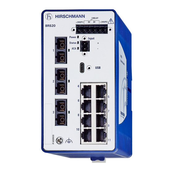
Device views 1.3.1 Front view Example of a low-port device variant 6-pin terminal block with screw lock for redundant power supply and signal contact 2-pin terminal block with screw lock for the digital input LED display elements for port status depending on device variant ... - Page 23 Example of a low-port device variant with PoE Input 2.5 GE 2.5 GE 2.5 GE 2.5 GE 6-pin terminal block with screw lock for redundant power supply and signal contact 2-pin terminal block with screw lock for the digital input USB-C interface LED display elements for port status BRS20/22/30/32...
-
Page 24: Rear View
1.3.2 Rear view Device variants with casing characteristic Device variants with casing with value C characteristic value E or D Rail lock slide for DIN rail mounting Installation BRS20/22/30/32/40/42/50/52 Release 06 03/2020... -
Page 25: Power Supply
Power supply 1.4.1 Supply voltage with characteristic value T The following options for power supply are available: 6-pin terminal block You will find information on connecting the supply voltage here: See “Supply voltage with characteristic value T” on page 41. 1.4.2 Supply voltage with characteristic value F The following options for power supply are available:... -
Page 26: Ethernet Ports
Ethernet ports You can connect end devices and other segments to the device ports using twisted pair cables or optical fibers (F/O). 1.5.1 10/100 Mbit/s twisted pair port This port is an RJ45 socket. The 10/100 Mbit/s twisted pair port allows you to connect network components according to the IEEE 802.3 10BASE-T/100BASE-TX standard. -
Page 27: 100 Mbit/S F/O Port
Pin assignment RJ45 10/100 Mbit/s 1000 MDI mode BI_DA+ TX− BI_DA− BI_DB+ — BI_DC+ — BI_DC− RX− BI_DB− — BI_DD+ — BI_DD− MDI-X mode BI_DB+ RX− BI_DB− BI_DA+ — BI_DD+ — BI_DD− TX− BI_DA− — BI_DC+ — BI_DC− Table 2: Pin assignment 10/100/1000 Mbit/s twisted pair port, RJ45 socket, MDI-X mode 1.5.3... -
Page 28: 100/1000 Mbit/S F/O Port
Example: Sending Receiving direction direction Power Input Power Input Status Status Table 3: Sending and receiving directions 1.5.4 100/1000 Mbit/s F/O port This port is an SFP slot. The 100/1000 Mbit/s F/O port allows you to connect network components according to standard IEEE 802.3 100BASE-FX/1000BASE-SX/1000BASE- This port supports: ... -
Page 29: Support Of Poe(+)
1.5.6 Support of PoE(+) The device variants BRS22/32/42/52 support Power over Ethernet (PoE) and Power over Ethernet Plus (PoE+). PoE-capable Ethernet ports are designed as 8 × RJ45 sockets. See “Front view” on page 22. The port allows you to connect network components via a PoE voltage source according to the standard IEEE 802.3af/at. -
Page 30: Display Elements
Display elements 1.6.1 Device state These LEDs provide information about conditions which affect the operation of the whole device. Power Power Power Status Status Status Figure 1: LED display elements for device status Display Color Activity Meaning Power Supply voltage —... -
Page 31: Port Status
1.6.2 Port status These LEDs display port-related information. Note: For device variants with 4 × RJ45 sockets: The LEDs are directly located at the ports. See figure 2 on page 31. For device variants with 8 × RJ45 sockets: The LEDs are located on the right side of the device. - Page 32 LS/DA LS/DA Figure 3: LED display elements for device variants with DSC, DST and 8 × RJ45 sockets LS/DA LS/DA Figure 4: LED display elements for device variants with SFP slots and 8 × RJ45 sockets Display Color Activity Meaning Link status —...
-
Page 33: Management Interfaces
Management interfaces 1.7.1 Signal contact RELAY 0.5 Nm 4.4 lb-in Figure 5: (1) Connection on the device, (2) terminal block mounted on the device (front view), tightening torque, (3) terminal block mounted on the device (view from above). The signal contact is a potential-free relay contact. The signal contact is open when the device is not connected to a power supply. -
Page 34: Usb-C Interface
1.7.2 USB-C interface Name Pin Pin Name V BUS V BUS ACA22-USB-C (EEC) V BUS V BUS Figure 6: (1) Position of the USB-C interface on the device, (2) pin assignment of the USB-C interface, (3) view of the ACA22-USB-C (EEC). The USB-C interface allows you to connect the AutoConfiguration Adapter ACA22-USB-C (EEC) storage medium. -
Page 35: Digital Input
Voltage not electrically insulated Supported file system: FAT32 Note: A USB cable is used exclusively for the configuration of your device. Note: The ACA22-USB-C (EEC) storage medium can remain permanently connected to the device. 1.7.3 Digital input Input 0.5 Nm 4.4 lb-in Figure 7: (1) Connection on the device, (2) terminal block mounted on the device... - Page 36 Power Status 2.5 GE Input 2.5 GE 2.5 GE 2.5 GE Power Input Status Input 2.5 GE 2.5 GE 2.5 GE 2.5 GE Figure 8: Presence of the digital input for PoE device variants Installation BRS20/22/30/32/40/42/50/52 Release 06 03/2020...
-
Page 37: Installation
Installation The devices have been developed for practical application in a harsh industrial environment. On delivery, the device is ready for operation. Perform the following steps to install and configure the device: Checking the package contents Installing and grounding the device ... - Page 38 Mounting Minimum clearance at Temperature derating the ventilation slots Standard mounting (vertical) 2 in (5 cm) 0.8 in (2 cm) 0 in (0 cm) 15 K 90° rotated mounting (horizontal) 0 in (0 cm) 15 K Table 6: Derating for different mounting positions Figure 9: Mounting on the DIN rail Proceed as follows: ...
-
Page 39: Grounding The Device
2.2.2 Grounding the device 0.5 Nm 4.4 lb-in Figure 10: Position of the ground connection on the device; tightening torque. All device variants have a functional ground connection. Proceed as follows: Ground the device via the ground screw. 2.2.3 Connecting the ferrite (optional) Exclusively applies to devices used in applications that require ship approval according to DNVGL, Bureau Veritas or Lloyd's Register. -
Page 40: Installing An Sfp Transceiver (Optional)
Installing an SFP transceiver (optional) Prerequisites: Exclusively use Hirschmann SFP transceivers. See “Accessories” on page 81. Figure 11: Installing SFP transceivers: Installation sequence Proceed as follows: Take the SFP transceiver out of the transport packaging (1). Remove the protection cap from the SFP transceiver (2). ... -
Page 41: Connecting The Terminal Blocks
Connecting the terminal blocks 2.4.1 Power supply Note: The supply voltage is connected to the device casing through protective elements exclusively. Supply voltage with characteristic value T RELAY +24 V(P1) +24 V(P2) 0V 0V 12 V DC ... 24 V DC 12 V DC ... - Page 42 Fasten the wires in the terminal block by tightening the terminal screws. Mount the terminal block on the device using screws. Supply voltage with characteristic value F RELAY +24 V(P1) +24 V(P2) 0V 0V 24 V DC ... 48 V DC 24 V DC ...
- Page 43 For the supply voltage to be connected, perform the following steps: Remove the terminal connector from the device. Connect the wires according to the pin assignment on the device with the clamps. Fasten the wires in the terminal block by tightening the terminal screws.
-
Page 44: Signal Contact (Optional)
Type of the voltages Specification of the supply Pin assignment that can be voltage connected Without using PoE or Rated voltage range DC: Plus terminal of the supply PoE+: 24 V DC ... 48 V DC voltage DC voltage Voltage range DC incl. Minus terminal of the supply maximum tolerances: voltage... -
Page 45: Digital Input (Optional)
2.4.3 Digital input (optional) Input 0.5 Nm 4.4 lb-in Figure 15: (1) Connection on the device, (2) terminal block mounted on the device (front view), tightening torque. Signal, terminal Function DI (+) Signal input DI (−) Reference potential Table 11: Digital input: pin assignment Proceed as follows: ... -
Page 46: Operating The Device
Connection constellations of sensors Input + 24 V + 24 V Figure 16: Connection of a sensor with separate power supply 1 - Sensor 2 - BRS20/22/30/32/40/42/50/52l 3 - Separate power supply for sensor Input +24 V Figure 17: Connection of a sensor with separate power supply 1 - Switch (2-wire sensor) 2 - BRS20/22/30/32/40/42/50/52l 3 - Separate power supply for sensor... -
Page 47: Connecting Data Cables
Connecting data cables Note the following general recommendations for data cable connections in environments with high electrical interference levels: Keep the length of the data cables as short as possible. Use optical data cables for the data transmission between the buildings. ... -
Page 48: Making Basic Settings
Making basic settings Note: 2 or more devices configured with the same IP address can cause unpredictable operation of your network. Install and maintain a process that assigns a unique IP address to every device in the network. The IP parameters must be entered when the device is installed for the first time. -
Page 49: First Login (Password Change)
Log on to the device again with your new password. Note: If you lost your password, then use the System Monitor to reset the password. For further information see: https://hirschmann-support.belden.com/en/kb/required-password- change-new-procedure-for-first-time-login Installation BRS20/22/30/32/40/42/50/52 Release 06 03/2020... -
Page 50: Monitoring The Ambient Air Temperature
Monitoring the ambient air temperature Operate the device below the specified maximum ambient air temperature exclusively. See “Climatic conditions during operation” on page 60. The ambient air temperature is the temperature of the air at a distance of 2 in (5 cm) from the device. -
Page 51: Maintenance And Service
Maintenance and service When designing this device, Hirschmann largely avoided using high-wear parts. The parts subject to wear and tear are dimensioned to last longer than the lifetime of the product when it is operated normally. Operate this device according to the specifications. ... -
Page 52: Disassembly
Disassembly Removing an SFP transceiver (optional) Figure 18: De-installing SFP transceivers: De-installation sequence Proceed as follows: Open the locking mechanism of the SFP transceiver (1). Pull the SFP transceiver out of the slot via the open locking mechanism (2). ... -
Page 53: Removing The Device
Removing the device Figure 19: Removal from the DIN rail Proceed as follows: Disconnect the data cables. Disable the supply voltage. Disconnect the terminal blocks. Disconnect the grounding. Insert a screwdriver horizontally below the casing into the locking gate. ... -
Page 54: Technical Data
Technical data General data General data Product name Weight Weight Plastic casing Metal casing BRS20-0400... 12.22 oz (380 g) 30.69 oz (870 g) BRS20-0500... 14.82 oz (420 g) 32.09 oz (910 g) BRS20-0600... 14.82 oz (420 g) 32.09 oz (910 g) BRS20-0800..S;C... -
Page 55: Supply Voltage
General data Dimensions See “Dimension drawings” on page 62. W × H × D Mounting See “Installing the device onto the DIN rail” on page 37. Pollution degree Degree of IP30 protection IP40 Note: IP protection is not evaluated by UL. Laser protection Class 1 in compliance with IEC 60825-1 Table 13: General data... - Page 56 Supply voltage with characteristic value F Overload current protection on the Non-replaceable fuse device Back-up fuse for each voltage input Nominal rating: 2 A ... 10 A Characteristic: slow blow Current integral I²t <1 A²s at 24 V DC Connection for functional ground See “Grounding the device”...
-
Page 57: Power Consumption/Power Output
Supply voltage with characteristic value P Voltage range DC incl. maximum When using PoE: 46 V DC ... 57 V DC tolerances: When using PoE+: 52 V DC ... 57 V DC Without using PoE or 19 V DC ... 60 V DC PoE+: Connection type 6-pin terminal block with screw lock... -
Page 58: Signal Contact
Device name Total power Thermal power PoE power output consumption output BRS42-00089999U... 106 W 55 Btu (IT)/h 90 W BRS42-00089999P... 249 W 31 Btu (IT)/h 240 W BRS42-0012OOOOU... 109 W 65 Btu (IT)/h 90 W BRS42-0012OOOOP... 252 W 41 Btu (IT)/h 240 W BRS52-0012OOOOU... -
Page 59: Digital Input
Digital input Digital input Connection type 2-pin terminal block with screw lock Tightening torque 4.4 lb-in (0.5 Nm) min. conductor 0.08 mm (AWG 28) diameter max. conductor AWG12 (2.5 mm²) diameter Maximum permitted input voltage range between -32 V DC and +32 V DC Nominal input voltage +24 V DC Input voltage, low level, status “0”... -
Page 60: Climatic Conditions During Operation
Climatic conditions during operation Climatic conditions during operation Minimum clearance at the See “Installing the device onto the DIN rail” on page 37. ventilation slots Ambient air temperature Standard up to 6562 ft ASL +32 °F ... +140 °F (0 °C ... (2000 m ASL) +60 °C) ... -
Page 61: Climatic Conditions During Storage
Climatic conditions during storage Climatic conditions during storage Ambient temperature −40 °F ... +185 °F (−40 °C ... up to 3 months +85 °C) -40 °F ... +158 °F (-40 °C ... up to 1 year +70 °C) -40 °F ... +122 °F (-40 °C ... up to 2 years +50 °C) +32 °F ... -
Page 62: Dimension Drawings
Dimension drawings 7.9.1 Device variants with casing with characteristic value C (plastic casing) inch 12,3 0.48 103,5 2.24 4.07 14,9 0.59 Figure 20: Narrow plastic casing Installation BRS20/22/30/32/40/42/50/52 Release 06 03/2020... - Page 63 inch 11,8 103,5 0.46 2.87 4.07 14,9 0.59 Figure 21: Medium plastic casing Installation BRS20/22/30/32/40/42/50/52 Release 06 03/2020...
- Page 64 inch 108,8 103,5 11,8 4.28 0.46 4.07 14,9 0.59 Figure 22: Wide plastic casing Installation BRS20/22/30/32/40/42/50/52 Release 06 03/2020...
-
Page 65: Device Variants With Casing With Characteristic Value E/D (Metal Casing)
7.9.2 Device variants with casing with characteristic value E/D (metal casing) inch 10,3 0.41 4,55 70,7 105,5 2.78 0.18 4.15 0.59 Figure 23: Narrow metal casing Installation BRS20/22/30/32/40/42/50/52 Release 06 03/2020... - Page 66 inch 86,6 0.39 4,55 105,5 3.41 0.18 4.15 0.59 Figure 24: Medium metal casing Installation BRS20/22/30/32/40/42/50/52 Release 06 03/2020...
- Page 67 inch 122,4 4,55 105,5 4.82 4.15 0.39 0.18 0.59 Figure 25: Wide metal casing Installation BRS20/22/30/32/40/42/50/52 Release 06 03/2020...
-
Page 68: Immunity
7.10 Immunity Immunity Standard applications Navy applications Railway applications (trackside) as per EN 50121-4 IEC 60068-2-6, test Fc Vibration 5 Hz ... 8.4 Hz with 0.14 in 2 Hz ... 13.2 Hz with 0.04 in — (3.5 mm) amplitude (1 mm) amplitude 8.4 Hz ... - Page 69 EMC interference immunity Standard Navy Railway applications applications applications (trackside) as per EN 50121-4 Electrostatic discharge EN 61000-4-2 Contact discharge ±4 kV ±6 kV ±6 kV EN 61000-4-2 Air discharge ±8 kV ±8 kV ±8 kV Electromagnetic field EN 61000-4-3 80 MHz ...
-
Page 70: Network Range
7.12 Network range Note: The line lengths specified for the transceivers apply for the respective fiber data (fiber attenuation and Bandwidth Length Product (BLP)/ Dispersion). 7.12.1 10/100/1000 Mbit/s twisted pair port 10/100/1000 Mbit/s twisted pair port Length of a twisted pair segment max. - Page 71 Product code Mode Wave length Fiber System Example for F/O Fiber attenuation BLP/Dispersion M-FAST-SFP-... attenuation cable length -LH/LC... 1550 nm 9/125 µm 10 dB ... 29 dB 29.20 mi ... 0.25 dB/km 19 ps/(nm×km) 64.62 mi (47 km ... 104 km) -LH/LC...
-
Page 72: Gigabit Ethernet Sfp Transceiver
Product code Mode Wave length Fiber System Example for F/O Fiber attenuation BLP/Dispersion attenuation cable length -L2, -LL 1550 nm 9/125 µm 3 dB ... 29 dB 8.70 mi ... 0.25 dB/km 19 ps/(nm×km) 64.62 mi (14 km ... 104 km) -G2, -GG 1550 nm 9/125 µm... - Page 73 Product code Mode Wave length Fiber System Example for F/O Fiber /Dispersion M-SFP-... attenuation cable length attenuation -LX+/LC... 1310 nm 9/125 µm 5 dB ... 20 dB 8.70 mi ... 0.4 dB/km 3.5 ps/(nm×km) 26.10 mi (14 km ... 42 km) -LH/LC...
-
Page 74: Gigabit Ethernet Sfp Transceiver
7.12.4 2.5 Gigabit Ethernet SFP transceiver Product code Mode Wave length Fiber System Example for F/O Fiber BLP/dispersion M-SFP-2.5-... attenuation cable length attenuation MM/LC EEC 850 nm 50/125 µm 0 dB ... 4 dB 0.34 mi (0.55 km) 3.5 dB/km 2000 MHz×km (OM3) MM/LC EEC... -
Page 75: Bidirectional Fast Ethernet Sfp Transceiver
7.12.5 Bidirectional Fast Ethernet SFP transceiver Product code Mode Wave length Wave length Fiber System Example for F/O Fiber Dispersion SFP-FAST-B... attenuation cable length attenuation SFP-FAST-BA 1310 nm 1550 nm 50/125 µm 0 dB ... 16 dB 0 mi ... 1.24 mi 1.0 dB/km 800 MHz×km MM/LC EEC... -
Page 76: Rating Due To Sfp Transceiver
Product code Mode Wave length Wave length Fiber System Example for F/O Fiber Dispersion SFP-GIG-B... attenuation cable length attenuation SFP-GIG-BB LX+/ 1550 nm 1310 nm 9/125 µm 3 dB ... 20 dB 7.45 mi ... 0.25 dB/km 19 ps/(nm×km) LC EEC 24.86 mi (12 km ... -
Page 77: Gigabit Ethernet Sfp Transceiver
Product code De-rating for a device with operating De-rating for a device with operating Order number temperature +140 °F (+60 °C) per SFP temperature +158 °F (+70 °C) per SFP transceiver used transceiver used M-FAST SFP-SM+/LC 943 867-001 M-FAST SFP-SM+/LC EEC 0 K 943 947-001 M-FAST SFP-LH/LC 943 868-001... -
Page 78: 2.5 Gigabit Ethernet Sfp Transceiver
Product code De-rating for a device with De-rating for a device with Order number operating temperature +140 °F operating temperature +158 °F (+60 °C) per SFP transceiver used (+70 °C) per SFP transceiver used M-SFP-TX/RJ45 943 977-001 M-SFP-TX/RJ45 EEC 942 161-001 SFP-GIG-LX/LC 942 196-001 SFP-GIG-LX/LC EEC... -
Page 79: Bidirectional Fast Ethernet Sfp Transceiver
7.13.4 Bidirectional Fast Ethernet SFP transceiver Product code De-rating for a device with operating De-rating for a device with operating Order number temperature +140 °F (+60 °C) per SFP temperature +158 °F (+70 °C) per SFP transceiver used transceiver used SFP-FAST-BA MM/LC EEC 942 204-001 SFP-FAST-BB MM/LC EEC... -
Page 80: Scope Of Delivery
Scope of delivery Scope of delivery 1 × Device 1 × Safety and general information sheet 1 × Terminal block for supply voltage and signal contact 1 × Terminal block for the digital input depending on device variant 1 × Ferrite with key Table 40: Scope of delivery Installation BRS20/22/30/32/40/42/50/52 Release 06 03/2020... -
Page 81: Accessories
Accessories General accessories General accessories AutoConfiguration Adapter ACA22-USB-C (EEC) 942-239-001 6-pin terminal block with screw lock (10 pieces) 972 272-303 6-pin terminal block with screw lock (50 pieces) 943 845-013 2-pin terminal block with screw lock (10 pieces) 972 272-201 2-pin terminal block with screw lock (50 pieces) 943 845-009 Industrial HiVision Network Management Software... -
Page 82: Fast Ethernet Sfp Transceiver
Fast Ethernet SFP transceiver Fast Ethernet SFP transceiver Order number M-FAST SFP-TX/RJ45 942 098-001 M-FAST SFP-TX/RJ45 EEC 942 098-002 The following operating conditions apply to twisted pair transceivers: Longer RSTP switching times and link loss detection times compared to twisted pair ports provided by the device directly. -
Page 83: Gigabit Ethernet Sfp Transceiver
Gigabit Ethernet SFP transceiver Order number M-SFP-LH+/LC EEC 942 119-001 SFP-GIG-LX/LC 942 196-001 SFP-GIG-LX/LC EEC 942 196-002 Table 44: Accessory: Gigabit Ethernet SFP transceiver a. You will find further information on certifications on the Internet on the Hirschmann product pages (www.hirschmann.com). 2.5 Gigabit Ethernet SFP transceiver 2.5 Gigabit Ethernet SFP transceiver Order number... - Page 84 Bidirectional Gigabit Ethernet SFP Transceivers Order number SFP-GIG-BA LX+/LC EEC 942 208-001 SFP-GIG-BB LX+/LC EEC 942 208-002 SFP-GIG-BA LH/LC EEC 942 209-001 SFP-GIG-BB LH/LC EEC 942 209-002 Table 47: Accessories: Bidirectional Gigabit Ethernet SFP transceivers a. You find further information on certifications on the Internet on the Hirschmann product pages (www.hirschmann.com).
-
Page 85: 10 Underlying Technical Standards
10 Underlying technical standards Name ANSI/UL 121201 Nonincendive Electrical Equipment for Use in Class I and II, Division 2 and Class III, Divisions 1 and 2 Hazardous (Classified) Locations DNVGL-CG-0339 Environmental test specification for electrical, electronic and programmable equipment and systems. FCC 47 CFR Part 15 Code of Federal Regulations NEMA TS 2... -
Page 86: A Further Support
A list of local telephone numbers and email addresses for technical support directly from Hirschmann is available at https:// hirschmann-support.belden.com. This site also includes a free of charge knowledge base and a software download section. Hirschmann Competence Center The Hirschmann Competence Center is ahead of its competitors on three counts with its complete range of innovative services: ... - Page 87 Installation BRS20/22/30/32/40/42/50/52 Release 06 03/2020...
Need help?
Do you have a question about the HIRSCHMANN BRS20 and is the answer not in the manual?
Questions and answers