
Related Manuals for Motorline professional MF2020


Summary of Contents for Motorline professional MF2020
- Page 1 MF2020 MF2020 USER’S AND INSTALER’S MANUAL V2.2 REV. 04/2022 Compatible hardware versions: V0.1.0 | V0.2.0...
-
Page 2: Table Of Contents
This product is certified in accordance with European Community (EC) safety standards. 02. THE PRODUCT This product complies with Directive 2011/65/EU of the MF2020 European Parliament and of the Council, of 8 June 2011, on TECHNICAL CHARACTERISTICS NUMBER OF SENSORS... -
Page 3: Safety Instructions
01. SAFETY INSTRUCTIONS GENERAL WARNINGS the risks and dangers involved. • Children shouldn’t play with the product or opening devices to avoid • This manual contains very important safety and usage information. the motorized door or gate from being triggered involuntarily. very important. - Page 4 01. SAFETY INSTRUCTIONS RESPONSABILITY work of Directive 2009/104/CE of European Parliament and of the Council of 16 September 2009. • Supplier disclaims any liability if: • Attach the permanent label for the manual release as close as • Product failure or deformation result from improper installation possible to the release mechanism.
-
Page 5: The Product Mf2020
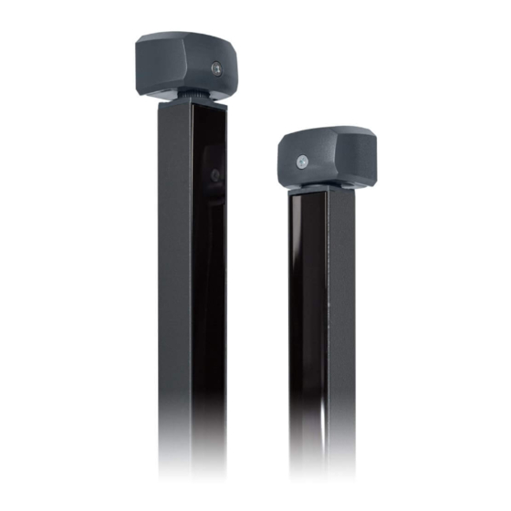
02. THE PRODUCT 02. THE PRODUCT MF2020 TECHNICAL CHARACTERISTICS The MF2020 is a column photocell developed to safeguard all types of industrial doors (sectional and SYNC CABLE high-speed doors) up to a maximum width of 10 meters. • Length 10 m The emitter and receiver create an infrared beam grid offering protection up to 2.5 meters high. -
Page 6: Dimensions And Description
02. THE PRODUCT 03. INSTALLATION DIMENSIONS AND DESCRIPTION CARE DURING INSTALLATION For the correct functioning of the photocells, it is necessary to pay attention to some aspects during the installation process. • COLUMN ALIGNMENT Make sure that the lower edge of the photocell columns is aligned with the level of the door in the closed position. - Page 7 03. INSTALLATION INSTALLATION Before starting the installation, turn off the main power supply to the door control board and make sure that this system is completely deactivated. • ASSEMBLY OF PHOTOCELL COLUMNS Remove covers (D) from columns (A) by loosening the screws on each cover.
- Page 8 03. INSTALLATION INSTALLATION • MAKE THE CONNECTIONS Pass the photocell cables through holes centered with the supports (B) SYNC CABLE of each column, in order to make the connections between them and with the control board. This way, they will be hidden by the covers (D). Make the cable connections in the following order: Connection a: TX Photocell (emitter) with Synchronization Cable;...
-
Page 9: Connections
04. CONNECTIONS 05. OPERATION CONNECTION SCHEME OPERATING MODE Photocells can operate in three different modes: CONNECTION COLOR • Power supply Relay output Relay output Power Supply GND (0V) Test input (NC) (COM) • GND (0V) Black • Relay output (NC) Green •... -
Page 10: Change Operating Mode 8B
05. OPERATION 05. OPERATION CHANGE OPERATING MODE RELAY OUTPUT To detect the current Operating Mode of the photocell, you must observe the behavior of the RX When an object enters the area protected by the light curtain the output switches to open contact (NO) Photocell Status LED: after the response time. -
Page 11: Led Signaling 9B
05. OPERATION 06. TROUBLESHOOTING LED SIGNALING INSTRUCTIONS FOR CONSUMERS AND SPECIALIZED TECHNICIANS (RX) (TX) LED Status Solution Photocell Status Green TX Green RX Yellow RX Sector 1 LED (4 sensor board) • Check electrical connections; Sector 2 LED (4 sensor board) •...
Need help?
Do you have a question about the MF2020 and is the answer not in the manual?
Questions and answers