Table of Contents
Advertisement
Quick Links
Advertisement
Table of Contents

Related Manuals for Motorline professional TEC100


Summary of Contents for Motorline professional TEC100
- Page 1 TEC100 TEC100 INSTALLER AND USER’S MANUAL v4.1 REV. 11/2020...
-
Page 2: Table Of Contents
ATTENTION: This product is certified in accordance with European 01. SAFETY INSTRUCTIONS Community (EC) safety standards. 02. TEC100 TECHNICAL CHARACTERISTICS This product complies with Directive 2011/65/EU of the 03. INSTALLATION European Parliament and of the Council, of 8 June 2011, on... -
Page 3: Safety Instructions
01. SAFETY INSTRUCTIONS GENERAL WARNINGS the motorized door or gate from being triggered involuntarily. • This manual contains very important safety and usage information. WARNINGS FOR TECHNICIANS very important. Read all instructions carefully before beginning the installation/usage procedures and keep this manual in a safe place •... - Page 4 01. SAFETY INSTRUCTIONS RESPONSABILITY • Attach the permanent label for the manual release as close as possible to the release mechanism. • Supplier disclaims any liability if: • Disconnect means, such as a switch or circuit breaker on the electrical •...
-
Page 5: Tec100
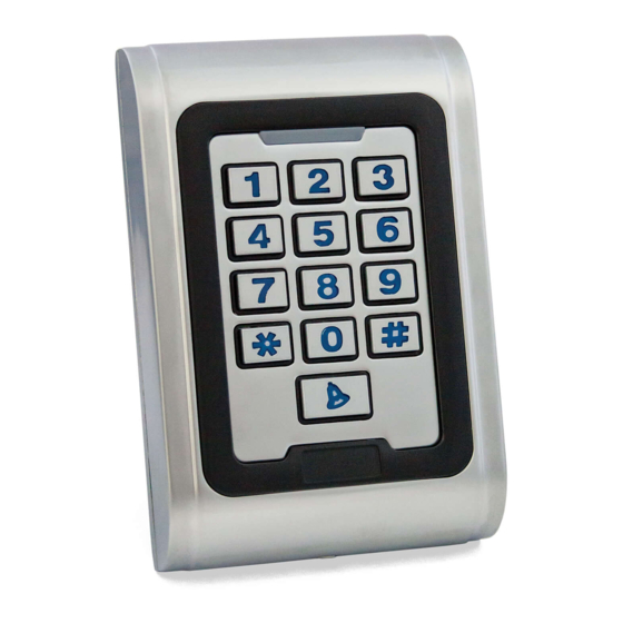
TECHNICAL CHARACTERISTICS TECHNICAL CHARACTERISTICS TEC100 is a multifunctional access controller by Wiegand keyboard or encoded card reader. It can be The dimensions of the TEC100 are as follows: installed internally or externally due to its galvanized zinc alloy structure wich makes it robust and anti- vandal.. -
Page 6: Installation
FIX THE REAR COVER Insert the bushings, position the cover on the holes and fix it with the screws. Insert the cable into the hole. FIT TEC100 Attach the TEC100 to the back cover, and tighten the set screws. -
Page 7: Acoustic-Optical Instructions
04. ACOUSTIC-OPTICAL INSTRUCTIONS 05. PROGRAMMING SOUNDS AND LIGHTS INITIAL SETTING At first use of the device, you must always change the master code for security, and set the operating OPERATION STATUS RED LIGHT GREEN LIGHT BELL mode for authorization of access. Standby Slowly blink OPERATIONS... -
Page 8: Door Opening 7A
• User with Card and PIN Read Card Add 1 User • Add Card User Be careful when using the TEC100 at high voltages (do not use in power contacts). > These users are only added with Card. Read Card 1 Add Multiple... - Page 9 05. PROGRAMMING 05. PROGRAMMING OPERATING MODE: CARD AND PIN INPUT OPERATING MODE: CARD INPUT In the , operating mode, input with card and pin, you can perform the following operations: In the , operating mode, card input, you can perform the following operations: These operations can only be done in Programming Mode.
-
Page 10: Eliminate All Users 9A
05. PROGRAMMING 05. PROGRAMMING DOOR WARNING OPEN TOO LONG TIME (DOTL) OPERATING MODE: CARD INPUT When used with an optional magnetic contact or magnetic contact built into the lock, if the door is User ID normally opened but not closed after 1 minute, the internal doorbell will be active automatically to •... -
Page 11: Keyboard Lock And Alarm Output Options 10A
To turn off the alarm when it has been triggered, perform this step in Stand-By mode. When there is an MCA connected with a TEC100 to operate only with code, we need to follow the following steps to register inputs and outputs. - Page 12 05. PROGRAMMING ACCESS CONTROL BY CODE (MCA) 06 • Access "Configuration" and select the 07 • Press "Edit" or double-click the person. "Personnel" tab. 08 • Fill in the required information and press "OK". Later, to identify yourself, you will have to enter the Card No.
-
Page 13: Connections
06. CONNECTIONS DESCRIPTION OF THE MAIN CABLE Line Sequence Marks Color Function description BELL_A Pink One end of the Bell button BELL_B Light pink Other end of Bell button Green Output line WG D0 White Output line WG D1 Negative alarm (positive alarm) ALARM Gray + 12 Vdc) - Page 14 06. CONNECTIONS CONNECTION SCHEME Power Supply Bell 12Vdc Alarm 24Vdc 2A máx. You can only connect the TEC100 to an Access Control device! Access control [ MCA ] Pink BELL_A [ ML4 ] [ MLS4 ] Light pink BELL_B [ TEC100 ]...
- Page 15 06. CONNECTIONS CONNECTION SCHEME Bell Alarm 24Vdc 2A máx. You can only connect the TEC100 to an Access Control device! Access control [ MCA ] Pink BELL_A [ ML4 ] [ MLS4 ] Light pink BELL_B [ TEC100 ] Green...
Need help?
Do you have a question about the TEC100 and is the answer not in the manual?
Questions and answers