Table of Contents
Advertisement
Quick Links
Advertisement
Table of Contents

Related Manuals for Motorline professional KFM


Summary of Contents for Motorline professional KFM
- Page 1 USER’S AND INSTALLER’S MANUAL V3.0 REV. 03/2020...
-
Page 2: Table Of Contents
00. CONTENT 01. SAFETY INSTRUCTIONS INDEX ATTENTION: 01. SAFETY INSTRUCTIONS This product is certified in accordance with European 02. PACKAGE Community (EC) safety standards. INSIDE PACKAGE This product complies with Directive 2011/65/EU of the 03. AUTOMATION European Parliament and of the Council, of 8 June 2011, on DIMENSIONS the restriction of the use of certain hazardous substances in TECHNICAL SPECIFICATIONS... -
Page 3: Safety Instructions
01. SAFETY INSTRUCTIONS GENERAL WARNINGS dangers involved. • Children shouldn’t play with the product or opening devices to avoid • This manual contains very important safety and usage information. the motorized door or gate from being triggered involuntarily. very important. Read all instructions carefully before beginning the installation/usage procedures and keep this manual in a safe place WARNINGS FOR TECHNICIANS that it can be consulted whenever necessary. - Page 4 01. SAFETY INSTRUCTIONS requirements for the use of work equipment workers at the work of product is in motion. Directive 2009/104/CE of European Parliament and of the Council of 16 RESPONSABILITY September 2009. • Attach the permanent label for the manual release as close as possible •...
-
Page 5: Package
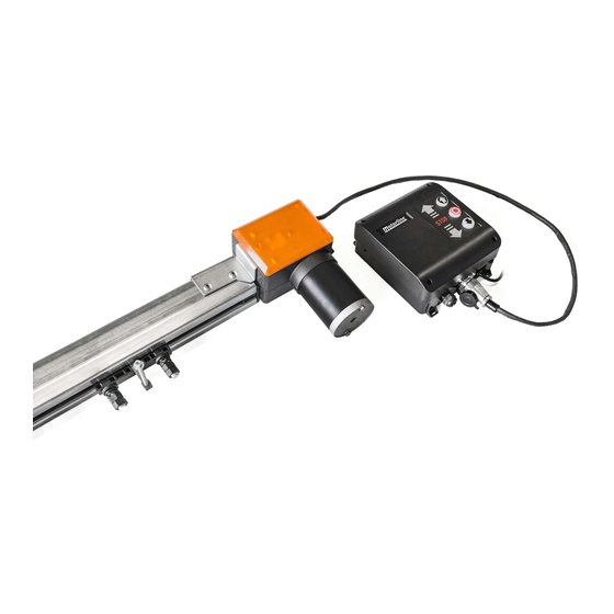
02. PACKAGE 03. AUTOMATION DENTRO DA EMBALAGEM DIMENSIONS KFM and rail dimensions are the following: Elements in the package of 1 motor: 01 • 01 Motoreducer 193mm 140mm 02 • 01 Motor's control board 03 • 02 4-Channel remote controls 04 •... -
Page 6: Installation
04. INSTALLATION CONNECTION SCHEME 1 • Motor 2 • Encoder (GND) PHOTOCELLs 3 • LED (+) 4 • Motor 5 • Encoder (+5V) EXTERIOR BUTTONS 6 • LED (-) 7 • Encoder (Signal) PB • Pushbutton PE • Photocells GND • Common +24V •... -
Page 7: Installation Of Supports 6B
04. INSTALLATION 04. INSTALLATION ENGINE'S INSTALLATION IN THE RAIL ENGINE'S INSTALLATION IN THE RAIL Fig. 4 Fig. 5 Fig. 10 1 • Remove the automation cover and loosen the 2 • Turn the automation over and open it by pulling 7 •... -
Page 8: Programming
05. PROGRAMMING 05. PROGRAMMING PREPARATION PROGRAM THE MOTOR'S COURSE In the scheme below you can see the automation programming panel, as well as the description of the programming buttons. CODE DOWN CODE DOWN CODE DOWN Fig. 16 Fig. 17 Fig. 18 1 •... -
Page 9: Delete Remote Controls 8A
05. PROGRAMMING 05. PROGRAMMING DELETE REMOTE CONTROLS DOOR LOCK When using external remote controls, it is recommended to use the door lock function. This function acts when the door closes completely, preventing from opening it again through external remote controls until it is deactivated again. ENABLE/DISABLE PHOTOCELLS CODE DOWN... -
Page 10: Troubleshooting
06. TROUBLESHOOTING INSTRUCTIONS FOR FINAL CONSUMERS INTRUCTIONS FOR SPECIALIZED INSTALLERS Anomaly Procedure Actions Procedure II Discovering the origin of the problem A) Has 24V: 1 • Remove the top cover of the to Motorline facilities for diagnosis the input, the transformer is the •... -
Page 11: Components Test
07. COMPONENTS TEST 24V MOTOR To detect which is the component with problems in a KFM automation install, it is sometimes necessary to run a test directly to an external power supply (another 24V battery). The scheme below shows how to connect the motor to the battery.
Need help?
Do you have a question about the KFM and is the answer not in the manual?
Questions and answers