Table of Contents
Advertisement
Quick Links
Advertisement
Table of Contents

Subscribe to Our Youtube Channel
Related Manuals for Motorline professional PERSA 400


Summary of Contents for Motorline professional PERSA 400
- Page 1 PERSA 400 USER’S AND INSTALLER’S MANUAL V4.2 REV. 05/2022...
-
Page 2: Table Of Contents
00. CONTENT 01. SAFETY INSTRUCTIONS INDEX ATTENTION 01. SAFETY INSTRUCTIONS This product is certified in accordance with European ATTENTION Community (EC) safety standards. 02. PACKAGE This product complies with Directive 2011/65/EU of the INSIDE PACKAGE European Parliament and of the Council, of 8 June 2011, on 03. -
Page 3: Safety Instructions
01. SAFETY INSTRUCTIONS GENERAL WARNINGS the motorized door or gate from being triggered involuntarily. • This manual contains very important safety and usage information. WARNINGS FOR TECHNICIANS very important. Read all instructions carefully before beginning the installation/usage procedures and keep this manual in a safe place •... - Page 4 01. SAFETY INSTRUCTIONS to the release mechanism. use or maintenance! • Disconnect means, such as a switch or circuit breaker on the electrical • Safety norms are not followed in the installation, use and panel, must be provided on the product’s fixed power supply leads in maintenance of the product.
-
Page 5: Package
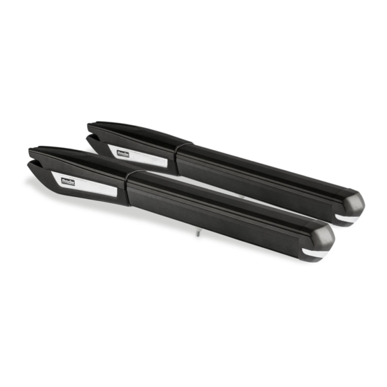
02. PACKAGE 03. AUTOMATISM INSIDE PACKAGE TECHNICAL SPECIFICATIONS In the package you will find the following components: PERSA specifications are as follow: 01 • 02 Swing motors PERSA400 02 • 01 Control board 230V AC 230V 50/60Hz 03 • 02 Remote controls (4 channels) 04 •... -
Page 6: Technical Specifications 4B
VERTICAL INSTALLATION DIMENSIONS PERSA 400 dimensions are the following: PERSA 400 automatism must be installed with a small inclination, to prevent water infiltration through the extension arm. For this, the front support must be fixed to the gate with a height lower than the height of the rear support. -
Page 7: Horizontal Installation Dimensions
* The installation of opening stopper is not mandatory. * The installation of opening stopper is not mandatory. During the installation process, it is During the installation process, it is PERSA 400 PERSA 400 required to respect the dimensions required to respect the dimensions... -
Page 8: Installation Steps
04. INSTALLATION 04. INSTALLATION INSTALLATION STEPS INSTALLATION STEPS Pay attention to the installation dimensions mentioned on pages 5B, 6A and 6B! 03 • Test the movement. • Place the dowels in each support with a small amount of lubricant so that there is no ex- cessive friction. -
Page 9: Micros Adjustment
04. INSTALLATION 04. INSTALLATION MICROS ADJUSTMENT MICROS ADJUSTMENT 01 • Unlock the motor (see page 5A). 02 • Remove the chrome clip with a screwdriver. 06 • Take the gate to the open position. 03 • Unfasten the two front screws, remove the cover and the profile cover. 07 •... -
Page 10: Installation Map
04. INSTALLATION INSTALLATION MAP CONTROL FLASHING MOTOR BOARD LAMP ANTENNA SELECTOR EXTERIOR PHOTOCELLS JUNCTION BOX EXTERIOR INTERIOR PHOTOCELLS PHOTOCELLS GATE STOPPER LEGEND: • Connection cables It is important to use stoppers at the opening and closing of the gate. If not res- It is important to use junction boxes for connections between motors, components pected, components of the automation may suffer efforts for which they were not and control board. -
Page 11: Connection Scheme
05. CONNECTION SCHEME 06. COMPONENTS TEST 110V/230V MOTOR MOTOR 24V To detect which are the components with problems in a 24V PERSA automatism installation, it is necessary to conduct tests with a direct connection to a external power supply (battery 24V). -
Page 12: 110V/230V Motor
06. COMPONENTS TEST 110V /230V MOTOR To detect if the malfunction is on the control board or on the motor NOTES: All tests must be performed by specialized is, sometimes, necessary to perform tests with direct connection technicians due to serious danger associated •... -
Page 13: Maintenance
07. MAINTENANCE MAINTENANCE • Lubricate dowels • Place a small amount of lubricant on the holes that contains support dowels. • Check motor supports • Make sure that supports remain well fixed on the pillars and gate to ensure proper functioning of the equipment. -
Page 14: Troubleshooting
08. TROUBLESHOOTING FINAL CONSUMERS INSTRUCTIONS INSTRUCTIONS FOR SPECIALIZED INSTALLERS Anomaly Procedure Behavior Procedure II Discovering the origin of the problem • Motor • Make sure you • Still not working. • Consult a qualified 1 • Open control board and check control board and test them by problem is on the control board.
Need help?
Do you have a question about the PERSA 400 and is the answer not in the manual?
Questions and answers