Table of Contents
Advertisement
Quick Links
Advertisement
Table of Contents

Related Manuals for Motorline professional SLIDE & OL


Summary of Contents for Motorline professional SLIDE & OL
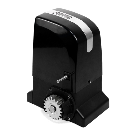
- Page 1 SLIDE & OL USER'S AND INSTALLER'S MANUAL V4.4 REV. 09/2024...
-
Page 2: Table Of Contents
00. CONTENT 01. SAFETY INSTRUCTIONS INDEX This product is certified in accordance with European Community 01. SAFETY INSTRUCTIONS (EC) safety standards. 02. PACKAGE This product complies with Directive 2011/65/EU of the European INSIDE PACKAGE Parliament and of the Council, of 8 June 2011, on the restriction 03. -
Page 3: Safety Instructions
01. SAFETY INSTRUCTIONS 01. SAFETY INSTRUCTIONS GENERAL WARNINGS • Children shouldn’t play with the product or opening devices to avoid the motorized door or gate from being triggered involuntarily. • This manual contains very important safety and usage information. • If the power cable is damaged, it must be replaced by the Read all instructions carefully before beginning the installation/ manufacturer, after-sales service or similarly qualified personnel usage procedures and keep this manual in a safe place that it can... - Page 4 01. SAFETY INSTRUCTIONS 01. SAFETY INSTRUCTIONS the power supply cable. Please note that all the cables must enter conditions have been met. the control board from the bottom. • In the event of tripping of circuits breakers of fuse failure, locate •...
-
Page 5: Package Inside Package
02. PACKAGE 03. OPERATOR INSIDE PACKAGE OPEN COVER Inside the package you will find the following components: During installation you will need to open the motor cover, to access various components 01• 01 motor 07• 02 fixation plate of the limit switches on the inside. -
Page 6: Unlock Operator 5A
03. OPERATOR 03. OPERATOR UNLOCK OPERATOR TECHNICAL SPECIFICATIONS To open manually the gate in case of electric power failure or in case of damage, follow the below Technical specifications of the automated operator: steps: 800A OL1500 OL2000 110V 230V 110V 230V 110V 230V... -
Page 7: Installation
04. INSTALLATION 04. INSTALLATION PRELIMINARY CHECKS SITE INSTALLATION – CREATE FOUNDATION To ensure safety and an efficiently operating automated system, make sure the following conditions are applied: • The structure of the gate must be suitable for being automated. In particular, check that the structure is sufficiently strong and rigid, and that its dimensions and weight conform to those indicated in the technical specifications;... -
Page 8: Site Installation - Existing Foundation 7A
04. INSTALLATION 04. INSTALLATION SITE INSTALLATION – EXISTING FOUNDATION APPLICATION OF MOTOR In case there is already a foundation at the installation site, proceed as below: 60mm 60mm 01 • Remove the motor covers (following the steps on page 4B), 02 •... -
Page 9: Installation Of Steel Gear Rack 8A
04. INSTALLATION 04. INSTALLATION INSTALLATION OF STEEL GEAR RACK INSTALLATION OF STEEL GEAR RACK Place the gate in the open position and unlock the motor! (p.05A). ) DETAIL 30 DETAIL 29 05 • Close the gate a bit, so that the rack is not being supported on the pinion anymore and apply another piece of rack (A). -
Page 10: Installation Of Nylon Gear Rack 9A
04. INSTALLATION 04. INSTALLATION INSTALLATION OF NYLON GEAR RACK INSTALLATION OF NYLON GEAR RACK Place the gate in the open position and unlock the motor! (p.05A) 04 • Close the gate a bit, so that the rack is not being supported on the pinion anymore and apply another piece of rack (A), fitting it into the rack already installed (B), as you can see in detail of image 01 •... - Page 11 04. INSTALLATION 04. INSTALLATION INSTALLATION OF PLATES THE LIMIT SWITCHES CLUTCH ADJUSTMENT To start the disassembly of the control board, disconnect the power and have maximum Place the gate in the open position and unlock the motor! (p.05A) care when handling it. Mechanical limit switch Magnetic limit switch Mechanical limit switch...
-
Page 12: Map Of Installation
04. INSTALLATION MAP OF INSTALLATION • FLASH LAMP • ANTENNA • CONTROL • MOTOR • PHOTOCELL • PHOTOCELL • KEY SELECTOR BOARD LEGEND: • Cables of connection It is important to use junction boxes for connections between motors, components It is important to use stoppers on the opening and closing of the gate. If this is not and control board. -
Page 13: Connections Of The Motor
05. CONNECTIONS OF THE MOTOR 05. CONNECTIONS OF THE MOTOR FOR 800A/OL1500 FOR OL2000 LS LO FO FC LS LO FO FC LA LE LS LO FO N ABCOM FE N N ABCOM FE N N ABCOM FE N µF 25µF MOTOR WIRES | CONNECTIONS µF... -
Page 14: Troubleshooting
06. TROUBLESHOOTING FINAL CONSUMERS INSTRUCTIONS SPECIALIZED TECHNICIANS INSTRUCTIONS Problem Procedure Behavior Procedure II Discovering the origin of the problem 1 • Open control board and check if 3 • Disconnect the motor from 4 • If the motor works, problem is 5 •... -
Page 15: Components Test
07. COMPONENTS TEST 08. MAINTENANCE SCHEMES FOR CAPACITORS MAINTENANCE To detect if the malfunction is on the control board or on the motor is, sometimes, necessary to perform tests with connection directly to a 110V/230V power supply. • Check all screws of the automation such For this, it is necessary to interpose a capacitor on the connection in order to the automatism to work as the fixing plate to the ground, the plates (check the type of capacitor to be used in the product manual).
Need help?
Do you have a question about the SLIDE & OL and is the answer not in the manual?
Questions and answers