Table of Contents
Advertisement
Quick Links
Advertisement
Table of Contents

Related Manuals for Brooks FAC20


Summary of Contents for Brooks FAC20
- Page 1 Instruction Manual FAC20 Rev 0 LARM ONTROLLER FAC20 MA455 Mar 2022...
- Page 2 This page has deliberately been left blank.
-
Page 3: Table Of Contents
Figure 7 Second FAC20 indication ........................9 Figure 8 Locating alarm source ........................10 Figure 9 Silence indication of active Alarm ....................10 Figure 10 Wiring fault of the external trigger ....................11 Figure 11 Firmware fault of FAC20 ........................ 11... -
Page 4: Introduction
Alarms to generate false alarms. With interconnected smoke/heat/CO Alarms, when one Alarm senses smoke / heat /CO, all Alarms will sound. The FAC20 is a three button Alarm Controller intended to provide the occupant with a full control over a hardwired interconnected Alarm system. -
Page 5: Overview
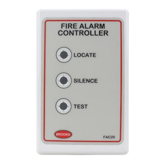
Instruction Manual FAC20 Rev 0 Overview The front display / control and rear view of FAC20 are shown in the Figure 1 below. Locate Button /Indicator Silence Button /Indicator Test Button /Indicator Front View Rear View Figure 1 Fire Alarm Controller front and rear view... -
Page 6: Figure 2 Dimensions Of Fac20
Instruction Manual FAC20 Rev 0 The rear and side view of the controller are shown in Figure 2 below. Figure 2 Dimensions of FAC20... -
Page 7: Installation And Wiring
The FAC20 is designed to be permanently mounted and connected to the Alarms mains power circuit. • The FAC20 is designed to suit a standard wall box or can be flush mounted on a gyprock wall. The controller must not be exposed to dripping or splashing. •... -
Page 8: Wiring And Termination
2. Select the nearest Alarm to FAC20 and run active (L), neutral (N) and interconnect (I) to where FAC20 is mounted. 3. Remove the first plug in FAC20 and terminate the incoming three wires L, N & I into the plug as shown in Figure 4, page 7. -
Page 9: Figure 4 Fac20 Connection Diagram
The interconnect wire must be treated as a mains powered conductor. It should be suitably rated and double insulated. Earthing of the FAC20 controller is not required. Up to 2 x FAC20 can be connected in the same Alarm circuit, provided all the alarms are EIB3000 series. -
Page 10: Operation
Instruction Manual FAC20 Rev 0 Operation Brooks recommend frequent testing of the system to ensure its continued and safe operation. The following are guidelines for testing the alarm controller: • After the system is installed. • Once monthly thereafter. •... -
Page 11: Locate The Source Alarm(S)
Figure 6 FAC20 Alarm Locate 2. If the “TEST” LED is flashing RED, it means the source of alarm is from the external alarm trigger e.g. sprinkler, panic, etc. connected to this FAC20. The FAC20 cannot control the alarm condition generated by external input. -
Page 12: Silence The Source Alarms(S)
The “SILENCE” LED will turn on RED for 10 minutes to indicate the source Alarm(s) will be silenced for 10 minutes. The silence condition of the Alarms and FAC20 will timeout automatically after the 10 minutes. If any alarm re-activates, the sequence will be repeated. Check the Alarms and replace if required. -
Page 13: Fault Indications
Figure 10 Wiring fault of the external trigger 2. If the “SILENCE” LED is steady ON yellow Figure 11 below, a firmware corruption is detected in the FAC20. The unit needs to be replaced. Figure 11 Firmware fault of FAC20... -
Page 14: Guarantee
If the product has any defect due to faulty workmanship or material it is to be returned to Brooks freight paid. Brooks will, at its sole discretion, repair or replace the item free of charge. On returning the complete product, proof of purchase will be required, all accessories MUST be returned. -
Page 15: Revision History
Instruction Manual FAC20 Rev 0 Revision history Issue Date Description Written By Checked By 28/7/21 Initial revision AS/HN... - Page 16 Instruction Manual FAC20 Rev 0 NSW - Head Office P.O. Box 7050 Silverwater NSW 1811 4 Pike Street Rydalmere NSW 2116 Ph: 02 9684 1466 Website: www.Brooks.com.au 9/71 Victoria Crescent, Abbotsford VIC 3067 Ph: 03 9879 5294 P.O. Box 101 Woodville SA 5011...
Need help?
Do you have a question about the FAC20 and is the answer not in the manual?
Questions and answers