Durr Dental VistaScan Mini Easy Installation And Operating Instructions Manual
Hide thumbs
Also See for VistaScan Mini Easy:

Related Manuals for Durr Dental VistaScan Mini Easy


Summary of Contents for Durr Dental VistaScan Mini Easy
- Page 1 VistaScan Mini Easy Installation and operating instructions 9000-618-210/02 *9000-618-210/02*...
- Page 3 Contents Contents Light protection cover ..Protection cover ... . . Storage box ....Important information About this document .
-
Page 4: Table Of Contents
Contents 11.5 Storage box with image plate storage tray ....12 Maintenance ..... 12.1 Recommended maintenance schedule . - Page 5 These operating instructions are valid for Order number VistaScan Mini Easy, order number: 2143-000-60 and VistaScan Mini Easy (China version), order number: 2143-000-54. Serial number Warnings and symbols Medical device...
- Page 6 – Personal injury due to lack of hygiene, e.g. Stacking limits infection Intended purpose Fragile, handle with care VistaScan Mini Easy The unit is intended exclusively for use in dental applications for the scanning and processing of Keep away from sunlight image data on an image plate.
- Page 7 Comply with all the relevant electrical safety ❯ regulations when working on the unit. VistaScan Mini Easy Never touch the patient and unshielded plug ❯ This unit is not suitable for monitoring patients connections on the device at the same time.
- Page 8 Essential performance char- children. acteristics Do not expose the unit to any strong vibrations ❯ The VistaScan Mini Easy unit does not possess or shocks. any significant performance characteristics as set out in IEC 60601-1 (EN 60601-1) section 4.3. 2.11...
- Page 9 Important information Perform regular data backups. ❯ Restrict access to units to trustworthy users, ❯ e.g. via a user name and password. Make sure that only trustworthy content is ❯ downloaded. Only install software and firmware updates that have been authenticated by the manufacturer.
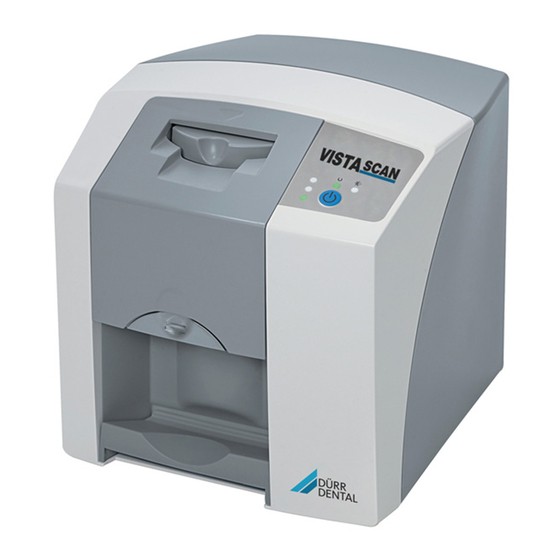
- Page 10 Product description Product description Overview VistaScan Mini Easy image plate scanner Input unit cover Plus intraoral image plate Light protection cover intraoral Storage box DBSWIN imaging software DVD VistaSoft imaging software DVD USB cable Network cable 10 Power supply unit with country-specific adapter...
- Page 11 ....2143-52 Intra / extra digital test body ..2121-060-54 – VistaScan Mini Easy basic unit – Power supply unit Consumables –...
- Page 12 Product description Plus image plate, size 2 3 x 4 cm (4 pcs.) ....2130-042-50 Plus image plate, size 2 3 x 4 cm (12 pcs.) ... . . 2130-042-55 Plus ID image plate, size 2 3 x 4 cm (4 pcs.) .
- Page 13 Product description Technical data Image plate scanner Electrical data for the device Voltage V DC Max. current consumption 1.25 Output < 30 Type of protection IP20 Electrical data – power supply unit Voltage V AC 100 - 240 Frequency 50/60 Protection class Type of protection IP20...
- Page 14 Product description General technical data Max. theoretical resolution Line approx. 40 pairs/mm (Lp/mm) Network connection LAN technology Ethernet Standard IEEE 802.3u Data rate Mbit/s Connector RJ45 Type of connection Auto MDI-X Cable type ³ CAT5 Serial interfaces Standard USB 2.0 Connection (on the unit) Standard type B Ambient conditions during operation...
- Page 15 Product description Electromagnetic compatibility (EMC) Interference immunity measurements on the cover Immunity to electrostatic discharge IEC 61000-4-2:2008 Compliant ± 8 kV contact ± 2 kV, ± 4 kV, ± 8 kV, ± 15 kV air Immunity to high-frequency electromagnetic fields IEC 61000-4-3:2006+A1:2007+A2:2010 3 V/m Compliant...
- Page 16 Product description Electromagnetic compatibility (EMC) Interference immunity measurements supply input Immunity to interference, surges IEC 61000-4-5:2005 Compliant ± 0.5 kV, ± 1 kV Immunity to interference, line-conducted disturbances induced by high-frequency fields – AC voltage grid IEC 61000-4-6:2013 0.15 - 80 MHz Compliant ISM frequency bands 0.15 - 80 MHz...
- Page 17 Product description Ambient conditions during storage and transport Temperature °C < 33 °F < 91 Relative humidity < 80 Dimensions of intraoral image plates Size 0 22 x 35 0.87 x 1.38 Size 2 31 x 41 1.22 x 1.61 Light protection cover Classification Medical product class...
- Page 18 Product description Operation Type plate The type plate is located on the rear of the Image plate scanner device. REF Order number Serial number Evaluation of conformity Intake slot This device has been subjected to conformity Operating elements acceptance testing in accordance with the cur- Release key rent relevant European Union guidelines.
- Page 19 Product description Operating elements Connections The connections are located on the rear of the unit, underneath the cover. Green operating LED Blue communication indicator On / off switch Green status LED Yellow status LED Connection for power supply unit Red status LED Reset button The status LEDs display the following status AUX connection for diagnostic units...
- Page 20 Product description This code allows you to clearly assign the correct Inactive side Black, printed with the image plate to the X-ray image. word "back" and the size and manufacturer's infor- mation Active side Light blue, with position- ing aid The positioning aid is visible on the X-ray image and makes it easier to align the image cor-...
- Page 21 Assembly Installation Assembly Carrying the unit Only qualified specialists or employees NOTICE trained by Dürr Dental are permitted to Risk of damage to sensitive compo- install, connect and start using the unit. nents in the unit as a result of shocks or vibrations Requirements Do not expose the unit to any strong...
- Page 22 Assembly Remove the cover from the rear of the device. Installing the unit with the wall mounting ❯ bracket The unit can be mounted on a wall with the wall mounting bracket (see "3.3 Optional items"). For installation refer to the installation instructions for the wall mounting (order number 9000-618-162) Electrical connections...
- Page 23 Assembly Combining devices safely A copy of the system manufacturer‘s Take care when connecting units together or to declaration in accordance with Article 12 parts of other systems as there is always an ele- of Directive 93/42/EEC can be found in ment of risk (e.g.
- Page 24 Assembly Connect the USB cable to the device. Commissioning ❯ NOTICE Short circuit due to the build up of condensation Do not switch on the unit until it has ❯ warmed up to room temperature and it is dry. The unit supports the following imaging pro- grams: –...
- Page 25 Assembly Mark the connected unit in the list. ❯ When the unit is first connected to a com- puter, it applies the language and time settings of the computer. Driver installation (USB port only) Only connect the USB cable to the com- puter when the installation wizard asks you to do so.
- Page 26 Assembly Configuring the appliance in Click Apply to save the configuration. ❯ DBSWIN Configuring the device with a network con- nection Configuration is carried out using VistaNetConfig, which is automatically installed during installation VistaNet device configuration window of DBSWIN or VistaEasy. allows you to change the device name ( name ), Select...
- Page 27 Assembly Click on Apply . ❯ The configuration is saved. Testing the device You can scan in an X-ray image to check that the unit is properly connected. Select the Test tab. ❯ Registered Units list. Select the unit from the ❯...
- Page 28 Assembly X-ray unit settings Intraoral X-ray units If 60 kV can be set on the X-ray unit, this setting is preferred. The standard exposure values for F-speed film (e. g. Kodak Insight) can be used. The following table shows the standard values for the exposure time and the dose area product of an image plate for an adult patient.
- Page 29 Assembly DC emitter, 6 mA Tube length 30 cm Without X-ray field X-ray field limitation X-ray field limitation limitation 70 kV 70 kV 70 kV mGycm mGycm mGycm Incisors 0.08 s 0.08 s 0.08 s Premolars 0.11 s 10.0 0.11 s 0.11 s Molars 0.14 s...
- Page 30 Usage Do not scratch the image plates. Do not sub- ❯ Usage ject the image plates to pressure from hard or pointed objects. Correct use of image plates CAUTION Image plates are toxic Image plates that are not packed in a light protection cover can lead to poi- soning when placed in the mouth or swallowed.
- Page 31 Usage 10 Operation Press the release button and remove the cover ❯ upwards at the same time. CAUTION The image data on the image plate is not permanent. The image data is altered by light, natu- ral X-ray radiation and scattered X-ray radiation.
- Page 32 Usage The light protection cover must be disinfected Preparing the X-ray ❯ using a disinfectant wipe immediately before it ü The image plate has been cleaned. is positioned inside the patient's mouth ü The image plate is not damaged. (e.g. with Dürr FD 350). ü...
- Page 33 Usage Preparing for scanning NOTICE CAUTION Powder from the protective gloves on the image plate can damage the unit Light erases the image data on the during scanning image plate Completely clean all traces of the pro- ❯ Never handle exposed image plates ❯...
- Page 34 Usage Remove the image plate and prepare it for tak- Scanning the image plate ❯ ing a new X-ray. To avoid the mix up of X-ray images, only scan the X-ray images from the selected patient. Place the light protection cover with the image ❯...
- Page 35 Usage 10.5 Switch off the unit. 11 Cleaning and disinfection Press the on/off switch for 3 seconds. ❯ When cleaning and disinfecting the unit and its While the unit is shutting down the operating accessories, observe country-specific directives, and communication LEDs flash. standards and specifications for medical prod- As soon as the unit has shut down it switches ucts as well as the specific specifications for...
- Page 36 Usage Clean the cover and inside parts with a moist, Input unit ❯ soft, lint-free cloth. The input unit must be cleaned and disinfected if there are indications of contamination or visible dirt. Use the following cleaning and disinfecting immersion disinfectants: ü...
-
Page 37: Storage Box With Image Plate
Usage product has been subjected to material compati- Disinfect the image plate storage tray using a ❯ bility testing by Dürr Dental. disinfection wipe. Alternatively, the image plate storage tray can NOTICE also be treated in a thermal disinfector or steam steriliser. -
Page 38: Maintenance
Usage 12 Maintenance 12.1 Recommended maintenance schedule Only trained specialists or personnel trained by Dürr Dental may service the device. Prior to working on the unit or in case of danger, disconnect it from the mains. The recommended maintenance intervals are based on using the device for 15 intraoral images per day on 220 working days per year. -
Page 39: Troubleshooting
Troubleshooting Troubleshooting 13 Tips for operators and service technicians Any repairs exceeding routine maintenance may only be carried out by qualified personnel or our service. Prior to working on the unit or in case of danger, disconnect it from the mains. 13.1 Poor X-ray image Error... - Page 40 Troubleshooting Error Possible cause Remedy Top or bottom bulge in the X- Image plate fed in off-centre and Insert the image plate cen- ❯ at an angle trally and straight. ray image Image plate exposed on the Insert the image plate cor- X-ray image is mirror-inverted ❯...
- Page 41 Troubleshooting Error Possible cause Remedy Shadow on the X-ray image Image plate removed from the Do not handle image plates ❯ light protection cover before without a light protection scanning cover. Store the image plate in a light ❯ protection cover. The metal part of the X-ray tube When taking an X-ray, make X-ray image cut off, part miss-...
- Page 42 Troubleshooting Error Possible cause Remedy Horizontal, grey lines on the Transport slipping Clean the transport mecha- ❯ nism, replace the transport X-ray image, extending beyond the left and right belts if necessary. image edge X-ray image is stretched Incorrect light protection cover Only use original accessories.
-
Page 43: Software Error
Troubleshooting Error Possible cause Remedy Lamination of the image plate Incorrect retainer system used Only use original image plates ❯ and film retainer systems. becoming detached at the edge Image plate handled incorrectly. Use the image plate correctly. ❯ Observe the operating ❯... -
Page 44: Fault On The Unit
Troubleshooting Error Possible cause Remedy The unit does not appear in Unit is connected behind a Configure the IP address with- ❯ router out an intermediate router on the options list in VistaConfig the unit. Reconnect the router. ❯ Manually enter the IP address ❯... - Page 45 Troubleshooting Error Possible cause Remedy Loud operating noises after Radiation deflector defective Inform a Service Technician. ❯ switching on lasting more than 30 seconds Unit not responding The unit has not yet completed After switching on, wait 20 - ❯ the startup procedure 30 seconds until the startup procedure has finished.
-
Page 46: Appendix
Appendix Appendix 14 Scanning times The scanning time corresponds to the time taken for complete scanning of image data and depends on image plate format and pixel size. The time to image will depend largely on the computer system used and its work load. Times stated are approximate. -
Page 47: File Sizes (Uncompressed)
Appendix 15 File sizes (uncompressed) The actual file size will depend on the image plate format and the pixel size. File sizes stated are approx- imate and have been rounded upwards. Suitable compression methods can considerably reduce the file size without loss of data. Theoretical resolution (LP/mm) Pixel size (μm) -
Page 48: Handover Record
Appendix 16 Handover record This document confirms that a qualified handover of the medical device has taken place and that appropriate instructions have been provided for it. This must be carried out by a qualified adviser for the medical device, who will instruct you in the proper handling and operation of the medical device. Product name Order number (REF) Serial number (SN) - Page 52 Hersteller/Manufacturer: DÜRR DENTAL SE Höpfigheimer Str. 17 74321 Bietigheim-Bissingen Germany Fon: +49 7142 705-0 www.duerrdental.com info@duerrdental.com...
Need help?
Do you have a question about the VistaScan Mini Easy and is the answer not in the manual?
Questions and answers