Durr Dental VistaScan Mini View Installation And Operating Instructions Manual
Hide thumbs
Also See for VistaScan Mini View:
- Installation and operating instructions manual (56 pages) ,
- Installation and configuration instructions (4 pages) ,
- Installation and operating instructions manual (52 pages)

Related Manuals for Durr Dental VistaScan Mini View


Summary of Contents for Durr Dental VistaScan Mini View
- Page 1 VistaScan Mini View Installation and operating instructions 2142100002L02 ...
-
Page 3: Table Of Contents
Contents Storage box ....20 Bite protector (optional) ..21 Important information 1 About this document ....3 Warnings and symbols . - Page 4 Contents 12.2 Light protection cover ..41 12.3 Image plate ....41 12.4 Protection cover ....41 12.5 Storage box with image plate storage tray .
-
Page 5: Important Information
The German version of the installation and oper- ating instructions is the original manual. All other Order number languages are translation of the original manual. These operating instructions apply to the follow- ing VistaScan Mini View units: Serial number Item number: – 2142-000-80 Medical device –... -
Page 6: Copyright Information
Important information Safety This way up / store and transport in an upright position Dürr Dental has designed and constructed this unit so that when used properly and for the in- Keep dry tended purpose it does not pose any danger to people or property. -
Page 7: Improper Use
Important information 2.5 Specialist personnel Bite protector The bite protector is a disposable item. Operation The bite protector is intended solely for use with Unit operating personnel must ensure safe and Dürr Dental image plates and Dürr Dental light correct handling based on their training and protection covers in dental applications. -
Page 8: Essential Performance Character
Do not expose the unit to any strong vibra- tions or shocks. The VistaScan Mini View unit does not possess any significant performance characteristics as 2.11 Disposal set out in EN/IEC 60601-1 section 4.3. The unit complies with the requirements accord- An overview of the waste keys for Dürr... -
Page 9: Protection From Threats From The Internet
Important information 2.12 Protection from threats from the Internet The unit is to be connected to a computer that can be connected to the Internet. Therefore, the system needs to be protected from threats from the Internet. Use antivirus software and update it regularly. Look for evidence of possible virus infection and, if applicable, check with the antivirus software and remove the virus. -
Page 10: Product Description
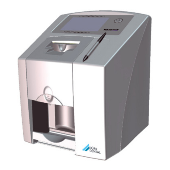
Product description Overview 2142100002L02 1908V007... - Page 11 Product description VistaScan Mini View image plate scanner Stylus Image plate intraoral Light protection cover intraoral Storage box SDHC memory card (fitted in the unit) DBSWIN imaging software DVD VistaSoft imaging software DVD Power supply unit with country-specific adapter 10 Network cable...
-
Page 12: Scope Of Delivery
Wall bracket ....2141-001-00 – VistaScan Mini View basic unit Storage box ....2141-002-00 –... -
Page 13: Wear Parts And Replacement
Product description Light protection covers Light Protection Cover Plus size 0 2 x 3 cm (100 pcs.) ... . 2130-080-00 Light Protection Cover Plus size 1 2 x 4 cm (100 pcs.) ... . 2130-081-00 Light Protection Cover Plus size 2 3 x 4 cm (300 pcs.) . -
Page 14: Technical Data
Product description Technical data 4.1 Image plate scanner Electrical data for the device Voltage V DC Max. current consumption 1.25 Output < 30 Type of protection IP20 Electrical data – power supply unit Voltage V AC 100 - 240 Frequency 50/60 Protection class Type of protection IP20 Output < 40 Max. current consumption Classification Medical product class Laser class (unit) - Page 15 Product description Network connection Connector RJ45 Type of connection Auto MDI-X ≥ CAT5 Cable type WLAN connection WLAN technology IEEE 802.11b/g Encryption WPA, WPA2 Memory card Type SDHC Maximum memory capacity File system FAT32 ≥ 4 Performance class Class Ambient conditions during operation Temperature °C +10 to +35 °F +50 to +95 Relative humidity...
- Page 16 Product description Electromagnetic compatibility (EMC) Interference immunity measurements cover Immunity to interference, high-frequency electromagnet- ic fields IEC 61000-4-3:2006+A1:2007+A2:2010 Compliant 3 V/m 80 MHz - 2.7 GHz 80% AM at 1 kHz Immunity to interference, near fields of wireless HF com- munication devices IEC 61000-4-3:2006+A1:2007+A2:2010 Compliant See immunity to interference table, near fields of wire- less HF communication devices.
- Page 17 Product description Electromagnetic compatibility (EMC) Interference immunity measurements supply input Immunity to interference by surges, line-earth IEC 61000-4-5:2005 Compliant ± 0.5 kV, ± 1 kV, ± 2 kV Immunity to interference, line-conducted disturbances induced by high-frequency fields – AC voltage grid IEC 61000-4-6:2013 0.15 - 80 MHz Compliant ISM frequency bands 0.15 - 80 MHz 80% AM at 1 kHz...
-
Page 18: Image Plate
Product description 4.2 Image plate Classification Medical devices class Ambient conditions during operation Temperature °C 18 - 45 °F 64 - 113 Relative humidity < 80 Ambient conditions during storage and transport Temperature °C < 33 °F < 91 Relative humidity < 80 Dimensions of intraoral image plates Size 0 22 x 35 Size 1 24 x 40 Size 2... -
Page 19: Type Plate
Product description Operation 4.4 Type plate The type plate is located on the rear of the de- 5.1 Image plate scanner vice. REF Order number Serial number 4.5 Evaluation of conformity This device has been subjected to conformity acceptance testing in accordance with the cur- rent relevant European Union guidelines. - Page 20 Product description If a scanning job is started via the imaging soft- Connections ware, the image is automatically transmitted to The connections are located on the rear of the the computer. unit, underneath the cover. If a scanning job is started via the touch screen, the image is saved to the memory card and then needs to be transferred to the computer.
-
Page 21: Image Plate
Product description 5.2 Image plate The image plate stores X-ray energy, which is re-emitted in the form of light after excitation via the laser. This light is then converted to image information in the image plate scanner. The image plate has an active side and an inac- tive side. -
Page 22: Light Protection Cover
Product description Clear assignment of image plate to image (Im- age Plate Plus ID only) On the Image Plate Plus ID there is also a hexa- decimal code on the image plate in addition to the marker. This code can be seen in the X-ray image. -
Page 23: Bite Protector (Optional)
Product description 5.7 Bite protector (optional) The bite protector protects the image plate size 4 as well as the light protection cover against heavy mechanical damage, e.g. if the patient bites down too hard during the X-ray ex- posure. 2142100002L02 1908V007... -
Page 24: Assembly
Assembly Installation Only qualified specialists or employees trained by Dürr Dental are permitted to 7.1 Carrying the unit install, connect and start using the unit. Requirements NOTICE Risk of damage to sensitive compo- 6.1 Installation/setup room nents in the unit as a result of shocks The room chosen for set up must fulfil the fol- or vibrations lowing requirements: Do not expose the unit to any strong vibrations or shocks. -
Page 25: Removing The Protective Film From The Touch Screen
Assembly Installing the unit with the wall mounting has been inserted in the unit incorrectly, take bracket it out again and re-insert it properly. The unit can be mounted on a wall with the wall mounting bracket (see "3.3 Optional items"). For installation refer to the installation in- structions for the wall mounting (order number 9000-618-162) 7.3 Removing the protective film... -
Page 26: Connecting The Device To The Network
Assembly – Mains voltage must match the information Insert the plug into the power outlet. shown on the type plate of the power supply Refit the cover. unit The cover on the rear must be correctly Attach the matching country-specific adapter fitted when the device is operated within to the power supply unit. -
Page 27: Commissioning
Assembly Commissioning If it is not 100% clear from the unit data sheet that such connections can be safely made or if you are in any doubt, always get a suitably NOTICE qualified person (e.g. the manufacturer) to ver- Short circuit due to the build up of ify that the setup is safe. - Page 28 Assembly Configuring WLAN on the unit An IP address can be entered manually and DHCP can be activated / deactivated working If the unit is to be operated via WLAN, the under Connection. WLAN stick included in the scope of delivery must be inserted into the USB connection on the back of the unit (see "Connections").
- Page 29 Assembly Activate the connected unit in the Registered Testing the device column. You can scan in an X-ray image to check that the unit is properly connected. You can also register multiple units. Select the Test tab. The VistaNet device configuration window al- lows you to change the device name (name), manually enter an IP address or call up informa- tion.
-
Page 30: X-Ray Unit Settings
Assembly 8.2 X-ray unit settings Intraoral X-ray units If 60 kV can be set on the X-ray unit, this setting is preferred. The standard exposure values for F-speed film (e. g. Kodak Insight) can be used. The following table shows the standard values for the exposure time and the dose area product of an image plate for an adult patient. -
Page 31: Acceptance Tests
Assembly DC emitter, 6 mA Tube length 30 cm Without X-ray field X-ray field limitation X-ray field limitation limitation 70 kV mGycm 70 kV mGycm 70 kV mGycm Incisors 0.08 s 0.08 s 0.08 s Premolars 0.11 s 10.0 0.11 s 0.11 s Molars 0.14 s 12.8 0.14 s 0.14 s Bitewing 0.14 s 12.8 0.14 s 0.14 s Check and adjust the specific X-ray unit in accordance with the standard values. -
Page 32: Usage
Usage Operating the touch screen NOTICE Damage to the touch screen due to incorrect handling Only operate the touch screen using your fingertips or the stylus. Do not use a sharp instrument (e.g. ballpoint pen) to operate the touch screen. Protect the touch screen against wa- ter. Operate the touch screen by tapping it with a fingertip or the stylus to select a menu or input field. -
Page 33: Entering Text In The Field
Usage 9.3 Entering text in the field 9.4 Calling up messages on the touch screen If an input is required, you can type informa- tion into the relevant field. The Messages view shows an overview of all The keyboard-window will open. previous messages. Here, the messages are di- vided into the following categories: Malfunction Unit will no longer func- tion. -
Page 34: Correct Use Of Image Plates
Usage 10 Correct use of image Do not scratch the image plates. Do not sub- ject the image plates to pressure from hard or plates pointed objects. CAUTION Image plates are toxic Image plates that are not packed in a light protection cover can lead to poi- soning when placed in the mouth or swallowed. -
Page 35: Operation
Usage 11 Operation – The marker (if present) is stuck in the correct position on the image plate. If the marker peels off, replace the image plate. CAUTION If using it for the first time or if it has been The image data on the image plate is stored for over a week: erase the image plate not permanent. - Page 36 Usage "12.2 Light protection cover"). Preparing for scanning CAUTION Light erases the image data on the image plate Never handle exposed image plates without the light protection cover. Wear protective gloves. Remove the image plate with the light protec- tion cover from the patient's mouth. WARNING Allow the light protection cover to fully dry. Contamination of the unit In the case of image plates Plus size 4, place Clean and disinfect the light protec-...
-
Page 37: Scanning The Image Data Via A
Usage NOTICE Powder from the protective gloves on the image plate can damage the unit during scanning Completely clean all traces of the pro- tective glove powder from your hands before handling the image plate. Tear off the light protection cover. 11.2 Scanning the image data via a computer Starting the image plate scanner and soft- ware The reading-out process is described us- Figure 2: Example of the animation requesting ing the VistaSoft imaging software. -
Page 38: Scanning Image Data Via The Touch Screen On The Unit
Usage 11.3 Scanning image data via the Slide the image plate out of its light protection cover downwards into the device until the im- touch screen on the unit age plate is automatically drawn in. Starting the image plate scanner When scanning the image data via the touch screen, there is no need for a PC connection. The image data is stored locally on the memory card. - Page 39 Usage The touch screen will display an animated The touch screen will display an animated visual symbol requesting insertion of the im- visual symbol requesting insertion of the im- age plate. age plate. Only insert the image plate when the Only insert the image plate when the bar above the animated sequence bar above the animated sequence...
-
Page 40: Erasing The Image Plate
Usage faces down, the inactive side of the image Remove the image plate and prepare it for plate faces the operator. taking a new X-ray. The fixing mechanism moves forwards auto- matically and takes hold of the light protec- tion cover with image plate. Slide the image plate out of its light protection cover downwards into the device until the im- age plate is automatically drawn in. -
Page 41: Switch Off The Unit
Usage – Due to an error, the image data on the image Pull the protective cover over the device so plate has not been erased (software error that it is completely covered. Make sure that message). the markings are at the front. Erasing the image plate via a computer Select the special ERASE mode in the soft- ware. -
Page 42: Cleaning And Disinfection
Usage 12 Cleaning and disinfection Use the following cleaning and disinfecting im- mersion disinfectants: When cleaning and disinfecting the unit and its – ID 213 Instrument disinfection accessories, observe country-specific directives, – ID 212 standards and specifications for medical prod- – ID 212 forte ucts as well as the specific specifications for dental practices and clinics. -
Page 43: Light Protection Cover
Usage Clean the cover, fixing mechanism and inside Only use a cleaning agent that is compatible parts with a soft, lint-free cloth that has been with the materials: dampened with cold tap water. Dürr Dental recommends the image plate clean- ing wipe (see "Cleaning and disinfection"). -
Page 44: Stylus
Usage Disinfect the image plate storage tray using a disinfection wipe. Alternatively, the image plate storage tray can also be treated in a thermal disinfector or steam steriliser. Do not exceed a temperature of 134°C when doing this. 12.6 Stylus The stylus can can be cleaned in the same way as the unit (see "12.1 Image plate scanner"). -
Page 45: En 13 Maintenance
Usage 13 Maintenance 13.1 Recommended maintenance schedule Only trained specialists or personnel trained by Dürr Dental may service the device. Prior to working on the unit or in case of danger, disconnect it from the mains. The recommended maintenance intervals are based on using the device for 15 intraoral images per day on 220 working days per year. -
Page 46: Troubleshooting
Troubleshooting 14 Tips for operators and service technicians Any repairs exceeding routine maintenance may only be carried out by qualified personnel or our service. Prior to working on the unit or in case of danger, disconnect it from the mains. 14.1 Poor X-ray image Fault Probable cause Solution X-ray image does not ap- Image plate inserted the wrong Scan the image plate again im- pear on the monitor after... - Page 47 Troubleshooting Fault Probable cause Solution Top or bottom bulge in the Image plate fed in off-centre and Check the error code on the X-ray image at an angle touch screen. Insert the image plate centrally and straight. X-ray image is mirror- Image plate exposed on the Insert the image plate correctly inverted wrong side.
- Page 48 Troubleshooting Fault Probable cause Solution X-ray image mirrored in Image plate bent during X-ray ex- Do not bend the image plate. one corner posure Image plate removed from the Do not handle image plates Shadow on the X-ray im- light protection cover before without a light protection cover. scanning Store the image plate in a light protection cover.
- Page 49 Troubleshooting Fault Probable cause Solution Software unable to com- The X-ray dose on the image Increase X-ray dose. bine the data to make a plate was insufficient complete image Amplification (HV value) is set too Increase amplification (HV value). low in the software Unsuitable scanning mode select- Select a suitable scanning mode.
- Page 50 Troubleshooting Fault Probable cause Solution X-ray image is stretched Incorrect light protection cover or Only use original accessories. lengthwise with bright, image plate used horizontal stripes X-ray image split vertically Dirt in the laser slit (e.g. hair, dust) Clean the laser slit. into two halves X-ray image with small Micro scratches on the image Replace the image plate. bright spots or clouding plate 2142100002L02 1908V007...
- Page 51 Troubleshooting Fault Probable cause Solution Lamination of the image Incorrect retainer system used Only use original image plates plate becoming detached and film retainer systems. at the edge Image plate handled incorrectly. Use the image plate correctly. Observe the operating instruc- tions for the image plates and film retainer systems. 2142100002L02 1908V007...
-
Page 52: Software Error
Troubleshooting 14.2 Software error Fault Probable cause Solution "Too much ambient light" Unit exposed to too much light Darken the room. Turn the unit so that no light can fall directly into the entry slot. "Incorrect power supply Incorrect power supply unit con- Use the supplied power supply unit"... -
Page 53: Fault On The Unit
Troubleshooting 14.3 Fault on the unit Fault Probable cause Solution Unit does not switch on No mains voltage Check the mains cable and plug connection and replace if necessary. Check the power supply unit. If the green status LED does not light up, replace the power supply unit. Check the mains fuse in the building. - Page 54 Troubleshooting Fault Probable cause Solution Network connection has WLAN stick not inserted Insert the WLAN stick into the been disconnected unit. Distance to WLAN router too Set up the unit closer to the great WLAN router. Walls between WLAN router and Set up the unit closer to the unit too thick WLAN router.
- Page 55 Troubleshooting 14.4 Error messages on the touch screen Fault Probable cause Solution Error code 1008 Connection interrupted Update the firmware. Error code 1010 Temperature of unit too high Allow the unit to cool down. Inform a Service Technician. Subassembly not initialised Fault in software, update the Error code 1022 software if required. Inform a Service Technician. Error code 1024 Internal data communication fault Switch the unit off and back on...
- Page 56 Troubleshooting Fault Probable cause Solution Error code 1160 Final radiation deflector rotation Inform a Service Technician. speed not attained Update the firmware. Replace the radiation deflector subassembly if the problem oc- curs regularly. Error code -1171 Fault on laser Send the unit for repair. Error code 1172 SOL sensor timeout Inform a Service Technician.
-
Page 57: Appendix
Appendix 15 Settings menu layout Device Information Unit data Dealer information Report Access level Operator Administrator Service technician Factory technician 2142100002L02 1908V007... - Page 58 Appendix System settings Language German (DE) English (EN) Date & time Date Time Network MAC address Name Interface WLAN DHCP IP address Subnet mask Gateway Acquisition settings Patient ID Surname First name Date of birth Male/female Pregnancy Comment X-ray station X-ray parameters Acquisition type INTRA...
- Page 59 Appendix Service menu Test Scanning modes Edit scanning modes Display scanning modes Maintenance Messages Diagnosis Statistics Display statistics coun- Display error counters Manipulation Transport Insert Erasure unit Pentaprism Query sensor values Sensors Temperatures Internal device voltages Oscilloscope Check touch screen Display test images Factory settings Reset scanning modes...
-
Page 60: Scanning Times
Appendix 16 Scanning times The scanning time corresponds to the time taken for complete scanning of image data and depends on image plate format and pixel size. The time to image will depend largely on the computer system used and its work load. Times stated are approximate. -
Page 61: File Sizes (Uncompressed)
Appendix 17 File sizes (uncompressed) The actual file size will depend on the image plate format and the pixel size. File sizes stated are ap- proximate and have been rounded upwards. Suitable compression methods can considerably reduce the file size without loss of data. Theoretical resolution (LP/ Pixel size (μm) 12.5... -
Page 62: Handover Protocol
Appendix 18 Handover record This document confirms the qualified handover and provision of instructions for the medical device from Dürr Dental. This must be carried out by a qualified adviser for the medical device, who will in- struct you in the proper handling and operation of the medical device. Product name Order number (REF) Serial number (SN) - Page 64 Hersteller/Manufacturer: DÜRR DENTAL SE Höpfigheimer Str. 17 74321 Bietigheim-Bissingen Germany Fon: +49 7142 705-0 www.duerrdental.com info@duerrdental.com...
Need help?
Do you have a question about the VistaScan Mini View and is the answer not in the manual?
Questions and answers