
Related Manuals for Teknik Hideaway Cotswold 5430446


Summary of Contents for Teknik Hideaway Cotswold 5430446
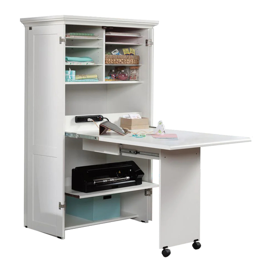
- Page 1 Teknik www.teknikoffice.co.uk Get crafty. Hideaway Cotswold Office/Craft Station NOTE: THIS INSTRUCTION BOOKLET CONTAINS IMPORTANT SAFETY INFORMATION. Model 430446 PLEASE READ AND KEEP FOR FUTURE REFERENCE.
- Page 2 Table of Contents Assembly Tools Required Part Identification No. 2 Phillips Screwdriver Hardware Identification Tip Shown Actual Size Hardware Usage Guide Assembly Steps 7-32 Hammer Not actual size Français 33-36 Español 37-40 Safety 41-42 Warranty Now you know Part Identification our ABCs.
- Page 3 Part Identification å While not all parts are labeled, some of the parts will have a label or an inked letter on the edge to help distinguish similar parts from each other. Use this part identification to help identify similar parts. Page 3...
- Page 4 Hardware Identification å Screws are shown actual size. You may receive extra hardware with your unit. 35AW CABINET RIGHT - 1 35AX CABINET LEFT - 1 35AY DRAWER RIGHT - 1 35AZ DRAWER LEFT - 1 (EXTENSION SET SHOWN SEPARATED) (EXTENSION SET SHOWN SEPARATED) LOCKING EXTENSION LOCKING EXTENSION...
- Page 5 Hardware Identification å Screws are shown actual size. You may receive extra hardware with your unit. TWIST-LOCK® MOLDING 16H HINGE - 2 67H HINGE - 4 FASTENER - 14 CONNECTOR - 2 MAGNETIC STRIKE 96K PULL - 2 14M PROPEL NUT - 4 CATCH - 2 PLATE - 2 GROMMET...
-
Page 6: Table Of Contents
Hardware Identification å Screws are shown actual size. You may receive extra hardware with your unit. 2S BLACK 1-7/8" FLAT HEAD SCREW - 9 BLACK 9/16" LARGE HEAD SCREW - 8 3S GOLD 5/16" FLAT HEAD SCREW - 16 BLACK 1-1/4" FLAT HEAD SCREW - 2 9S BLACK 1-1/8"... - Page 7 Hardware Usage Guide HOW TO USE A TWIST-LOCK FASTENER ® Push a TWIST-LOCK® FASTENER 1. Insert the dowel end of the FASTENER into the into the large hole in the part. hole of the adjoining part. NOTE: The dowel end of the FASTENER must remain fully inserted in the hole of the adjoining part while locking the FASTENER.
-
Page 8: Gold 5/16" Flat Head Screw
Step 2 å Separate the LOCKING EXTENSION SLIDES (Z) from the LOCKING EXTENSION RAILS (Y) as shown in the upper diagram below. Be prepared, the parts are greasy. å Fasten the LOCKING EXTENSION RAILS (Y) to the ENDS (A and B). Use four GOLD 5/16" FLAT HEAD SCREWS (3S). å... - Page 9 Step 3 å Fasten the FIXED SHELF (D) and BOTTOM (E) to the Caution LEFT END (B). Tighten four TWIST-LOCK® FASTENERS. Do not stand the unit upright without the BACK fastened. The unit may collapse. S u r f a c i t h I S T - L O...
- Page 10 Step 4 å Push two SAUDER TWIST-LOCK® FASTENERS (12F) into the large holes in the SHELF UPRIGHT (N). å Fasten the SHELF UPRIGHT (N) to the FIXED SHELF (D). Use two BLACK 1-7/8" FLAT HEAD SCREWS (2S). i t h o ®...
- Page 11 Step 5 å Fasten the RIGHT END (A) to the FIXED SHELF (D) and BOTTOM (E). Tighten four TWIST-LOCK® FASTENERS. Open end Open end Page 11...
- Page 12 Step 6 å Tap two MOLDING CONNECTORS (16F) into the notches in the MOLDINGS (S, T, and U). Use your hammer to tap the MOLDING CONNECTORS (16F) into the notches in the MOLDINGS. Flat end Flat end Unfinished surface Page 12...
-
Page 13: Black 1-1/8" Pan Head Screw
Step 7 å Fasten the RIGHT MOLDING (T) to the RIGHT END (A). Use two BLACK 2" PAN HEAD SCREWS (66S). å Fasten the LEFT MOLDING (U) to the LEFT END (B). Use two BLACK 2" PAN HEAD SCREWS (66S). BLACK 2"... -
Page 14: Silver 2" Flat Head Screw
Step 8 å Open the FURNITURE TIPPING RESTRAINT KIT (97), and fasten the SAFETY STRAP to the TOP (C). Use the provided SHORT SCREW. å NOTE: Position the SAFETY STRAP exactly as shown. å Fasten the TOP (C) to the UPRIGHT (N). Tighten two TWIST- LOCK®... - Page 15 Step 9 å Carefully turn your unit over onto its front edges. Caution å Unfold the BACK (F) and lay it over your unit. Do not stand the unit upright without the BACK fastened. The unit may collapse. å A perforation in the BACK (F) has been provided for access to the SAFETY STRAP.
- Page 16 Step 10 å Place a LEVELER BRACKET (17E) over the holes in the bottom edges of the ENDS (A and B). å Use a hammer to drive a PROPEL NUT (14M) through each BRACKET and into the holes in the ENDS. Now, turn a LEVELER (18E) into each PROPEL NUT.
- Page 17 Step 11 å Carefully stand your unit upright in its final location against a wall. We recommend using the SAFETY STRAP for added stability. å NOTE: Do not turn the SAFETY DRYWALL ANCHOR into a wall stud. If you prefer to fasten the SAFETY STRAP to a wall stud, go to your local hardware store for proper hardware.
- Page 18 Step 12 å Fasten the LOCKING EXTENSION SLIDES (Z) to the PULL-OUT TOP (I). Use four BLACK 7/8" LARGE HEAD SCREWS (17S) through holes #1 and #4. å Fasten the PULL-OUT BACK (J) to the PULL-OUT TOP (I). Use three SILVER 2" FLAT HEAD SCREWS (57S). SILVER 2"...
- Page 19 Step 13 å Push four SAUDER TWIST-LOCK® FASTENERS (12F) into the large holes in the OUTER UPRIGHTS (L). Do not tighten the TWIST-LOCK® FASTENERS in this step. Page 19...
- Page 20 Step 14 å Separate the EXTENSION SLIDES (40MC) from the EXTENSION RAILS (40MA) as shown in the upper diagram below. Be prepared, the parts are greasy. å Fasten the EXTENSION RAILS (40MA) to the OUTER UPRIGHTS (L). Use four GOLD 5/16" FLAT HEAD SCREWS (3S) through holes #1 and #4. å...
- Page 21 Step 15 å Fasten the OUTER UPRIGHTS (L) to the PULL-OUT TOP (I). Tighten four TWIST-LOCK® FASTENERS. Open end Surface with TWIST-LOCK® FASTENERS Surface without TWIST-LOCK® FASTENERS Page 21...
- Page 22 Step 16 å Fasten the DRAWER RIGHT (35AY) and DRAWER LEFT (35AZ) to the SLIDE-OUT SHELF (O). Use four BROWN 1" FLAT HEAD SCREWS (18S) through holes #2 and #4. å Fasten the SLIDING SHELF BACK (P) to the SLIDE-OUT SHELF (O).
- Page 23 Step 17 å To insert the PULL-OUT TOP (I) into your unit, line up the LOCKING EXTENSION SLIDES (Z) on the TOP with the LOCKING EXTENSION RAILS (Y) on the unit and push the TOP into the unit until the drawer is fully inserted. The drawer will push in hard until it is all the way in, then it will slide in and out easier.
- Page 24 Step 18 å Turn four SILVER 5/8" FLAT HEAD SCREWS (23S) halfway into the holes in the PULL-OUT BACK (J). Do not completely tighten the SCREWS. å Then, slide the OUTLET (1D) onto the heads of the SCREWS in the PULL-OUT BACK (J). å...
- Page 25 Step 19 å Fasten the EXTENSION SLIDES (40MC) to the INNER UPRIGHTS (M). Use four GOLD 5/16" FLAT HEAD SCREWS (3S) through holes #1 and #4. Open end Open end The holes should be closer to this edge. The holes should be closer to this edge.
- Page 26 Step 20 å Fasten the INNER UPRIGHTS (M) to the LEG (R). Use four BLACK 1-7/8" FLAT HEAD SCREWS (2S). å Place a CASTER BRACKET (16C) over each hole in the end of the LEG (R). Carefully insert a CASTER (15C) through each BRACKET on the LEG and into the holes in the edge of the LEG.
- Page 27 Step 21 å To insert the INNER UPRIGHTS (M) into your unit, line up the EXTENSION SLIDES (40MC) on the INNER UPRIGHTS with the EXTENSION RAILS (40MA) on the OUTER UPRIGHTS (L) and push the INNER UPRIGHTS into the unit until the INNER UPRIGHTS are fully inserted. The UPRIGHTS will push in hard until they are all the way in, then they will slide in and out easier.
- Page 28 Step 22 å Fasten the HINGES (16H) to the FLIP-UP TOP (K). Use four BLACK 9/16" LARGE HEAD SCREWS (1S). å Fasten the LEG STOP (V) to the FLIP-UP TOP (K). Use two BLACK 1-1/4" FLAT HEAD SCREWS (7S). BLACK 9/16" LARGE HEAD SCREW (4 used in this step) BLACK 1-1/4"...
- Page 29 Step 23 å Fasten the FLIP-UP TOP (K) to the PULL-OUT TOP (I). Use four BLACK 9/16" LARGE HEAD SCREWS (1S) through the HINGES and into the PULL-OUT TOP. BLACK 9/16" LARGE HEAD SCREW (4 used in this step) Page 29...
-
Page 30: Silver 9/16" Large Head Screw
Step 24 å Fasten four HINGES (67H) to the DOORS (G and H). Use eight SILVER 9/16" LARGE HEAD SCREWS (54S). å Fasten the STRIKE PLATES (6I) to the DOORS (G and H). Use two BLACK 1/2" FLAT HEAD SCREWS (11S). SILVER 9/16"... - Page 31 Step 25 å Fasten the LEFT DOOR (H) to the LEFT END (B). Use four SILVER 9/16" LARGE HEAD SCREWS (54S). å NOTE: To make adjustments to the DOORS, loosen the SCREWS in the HINGES, make needed adjustments, and tighten the SCREWS. å...
- Page 32 Step 26 å Push a RUBBER SLEEVE (2R) over one end of each METAL PIN (1R). Insert the METAL PINS into the hole locations of your choice in the ENDS (A and B) and SHELF UPRIGHT (N). Set the ADJUSTABLE SHELVES (Q) onto the METAL PINS. å...
- Page 33 WARNING Please use your furniture correctly and safely. Improper use can cause safety hazards, or damage to your furniture or household items. Carefully read the following safety information. Death or serious injury may occur when children climb on furniture. A remote control, toys or other items placed on the furniture may encourage a child to climb on the furniture which could cause it to tip-over and result in serious injury or death.
Need help?
Do you have a question about the Hideaway Cotswold 5430446 and is the answer not in the manual?
Questions and answers