
Related Manuals for Polycom SpectraLink 1725-36033-001


Summary of Contents for Polycom SpectraLink 1725-36033-001
- Page 1 SpectraLink 8000 SVP Server ® SVP100, SVP020, SVP010 Administration Guide for SIP March 2012 Edition 1725-36033-001 Version G...
- Page 2 US and foreign patents and/or pending patent applications held by Polycom, Inc. Copyright Notice © 2009 to 2012, Polycom, Inc. All rights reserved. POLYCOM®, the Polycom "Triangles" logo and the names and marks associated with Polycom's products are trademarks and/or service marks of Polycom, Inc.
-
Page 3: About This Document
Related Documents SpectraLink 8020/8030 Wireless Telephone: Administration Guide for SIP (1725-36038-001) Available at. http://www.polycom.com/usa/en/support/voice/wi-fi/wi-fi.html Polycom VIEW Certified Products Guide (1725-36040-001) VIEW Configuration Guide 1725-36xxx-001 where xxx indicates a number corresponding to the type of access point) Available at http://www.polycom.com/support/voice/wi-fi/view_certified.html Deploying Enterprise-Grade Wi-Fi Telephony... -
Page 4: Customer Support
SpectraLink 8000 SVP Server: Administration Guide for SIP Customer Support Polycom wants you to have a successful installation. If you have questions, please contact our Customer Support Hotline at 1-888-POLYCOM (1-888-765-9266). The hotline is open Monday through Friday, 6 a.m. to 6 p.m. -
Page 5: Table Of Contents
Contents About This Document ... 3 Polycom Model Numbers ...3 Related Documents ...3 Customer Support ...4 Icons and Conventions ...4 SpectraLink 8000 SVP Server Overview ... 7 SpectraLink Voice Priority (SVP) and Quality of Service ...7 SpectraLink 8000 SVP Server Models ...8 The Timing Function ...8... - Page 6 SpectraLink 8000 SVP Server: Administration Guide for SIP The NetLink SVP-II System Menu ...24 Network Configuration ...25 SendAll ...26 SVP Server Configuration ...29 QoS Configuration ...33 Change Password...35 Swapping/Adding/Deleting SVP Servers ... 37 Adding an SVP Server ...37 Removing an SVP Server ...37 SVP Server Failure ...38...
-
Page 7: Spectralink 8000 Svp Server Overview
SpectraLink 8000 SVP Server Overview The SpectraLink 8000 SVP Server is an Ethernet LAN device that works with access points (APs) to provide QoS on the wireless LAN. Voice packets to and from the SpectraLink 8000 Wireless Telephones are intercepted by the SVP Server and encapsulated for prioritization as they are routed to and from an IP telephony server. -
Page 8: Spectralink 8000 Svp Server Models
Multiple SVP Servers Multiple SVP Server environments are those which have more than one SVP Server. Up to four SVP010 models or up to two SVP020 models may be installed in any one subnet. Up to 16 models of SVP100 Servers may be installed in any one subnet. All SVP Servers must be in the same subnet. - Page 9 A SpectraLink handset registers to a single SVP Server the first time it is powered on. Once the handset has contacted this Registration Server, it obtains a list of all SVP Servers in the system. The handset then maintains this list in non-volatile memory and updates it only when rebooted.
-
Page 10: Multiple Svp Server Capacities
SpectraLink 8000 SVP Server: Administration Guide for SIP Multiple SVP Server Capacities The system capacity of each SVP Server model is shown in the tables below. Note that SVP Server models may not be combined within one subnet. SpectraLink SVP010 and SVP020 Server capacity The system capacity of the SVP010 and SVP020 is measured by number of powered-on handsets. - Page 11 1000 1500 2000 2500 3000 3500 4000 4500 5000 5500 6000 6500 7000 7500 8000 SpectraLink 8000 SVP Server Overview Possible installed handsets @ 15% @ 20% in active in active calls calls 1067 1407 1055 1747 1310 2080 1560...
-
Page 12: Notes On System Configuration
Multiple SVP Server environments are those which have more than one SVP Server. SVP Server models may not be combined within one subnet. More than one SVP Server model type may be used within a facility if installed on different subnets. Wireless telephones cannot roam with uninterrupted service between subnets unless specific LAN components are present. -
Page 13: System Diagram
System Diagram The following diagram shows multiple SVP Servers residing on a network with an IP telephony gateway and IP telephony server, wireless LAN APs, and Ethernet switch: Access point SpectraLink Wireless Telephones Access point Optional Wireless SpectraLink Wireless Telephones... -
Page 14: System Components
The SpectraLink 8000 System must connect to APs that utilize SpectraLink Voice Priority (SVP). Contact Polycom, or a certified Polycom distributor, to verify that your AP and its software version are supported. Ethernet switch A component in the wired Ethernet LAN infrastructure. -
Page 15: Administrative Computer
Some installations use a laptop to configure and maintain system components. TFTP server Required in an IP system to distribute software to the wireless telephones and SVP Server. May be on a different subnet than the IP gateway, IP telephony server, and APs. PN: 1725-36033-001_G.doc... -
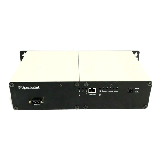
Page 16: The Front Panel Of The Svp Server
LNKOK NETWORK ERROR STATUS system. Use only the Polycom-provided Class II AC Adapter with output 24V DC, 1A. NETWORK Port: male DB-9 connector (DTE) used for RS-232 connection to : Lit when there is a network connection. : Lit if there is system activity. - Page 17 SpectraLink 8000 SVP Server Overview Note that the model designation may be found on the label which is on the side of the SVP Server. PN: 1725-36033-001_G.doc...
-
Page 19: Installing The Spectralink 8000 Svp Server
Required Materials The following equipment must be provided by the customer. Power outlet – AC adapter provided by Polycom. Backboard space – the SVP Server is designed to be wall- mounted to ¾" plywood securely screwed to the wall. -
Page 20: Locate The Svp Server
• switch. Install the SVP Server The SVP Server may be mounted on a rack or to a wall. Mount the SVP Server on a rack The rack-mount kit is designed for mounting equipment in a standard 19- inch rack and should contain the following equipment: ... - Page 21 Mount the SVP Server to a wall The SVP Server can be mounted either horizontally or vertically. To mount the SVP Server to a wall: 1. Using a 1/8-inch drill bit, drill four pilot holes, on 1.84-inch by 12.1-inch centers (approximately equivalent to 1-13/16” by 12-1/8”).
-
Page 22: Connect Power
SpectraLink 8000 SVP Server: Administration Guide for SIP Connect SVP Server to LAN Using a Cat. 5 cable, connect the the connecting port on the Ethernet switch. Connect power 1. Once the units have been properly grounded, connect the power plug from the AC adapter to the jack labeled Server. -
Page 23: Configuring The Spectralink 8000 Svp Server
TFTP. Connecting to the SVP Server The initial connection to the SVP Server must be made via a serial connection to establish the SVP Server’s IP address. After the IP address is established, connection to the SVP Server may be done via the network using telnet. -
Page 24: The Netlink Svp-Ii System Menu
SpectraLink 8000 SVP Server: Administration Guide for SIP Connecting via telnet Telnet can only be used after the SVP Server’s IP address is configured. The telnet method of connection is used for routine maintenance of the SpectraLink Server for both local and remote administration, depending on your network. -
Page 25: Network Configuration
The IP address and other network settings are established via the Network Configuration establish a hostname and enter the IP address of the location of any software updates you may obtain from Polycom. See Chapter 5 Software Maintenance for more information about installing software updates via TFTP. -
Page 26: Sendall
NONE The following options must be configured: IP Address Enter the IP address of the SVP Server, defined by your network administrator. Enter the complete address including digits and periods. The SVP Server will automatically lock for maintenance if the IP address is changed. -
Page 27: Subnet Mask
: disables. : The IP address of a network TFTP server that will be . This will cause the DHCP client in the SVP Server to DHCP . This will cause the DHCP client in the SVP Server to attempt to... -
Page 28: Syslog Server
The SVP Server must be reset in order to set the configuration options. If the SVP Server is in selecting the pressing Y upon exit. (see DHCP . If Syslog is set, a message is sent to the syslog server when an Maintenance Lock option in the Reset SVP-II Configuration above) -
Page 29: Svp Server Configuration
SVP Server Configuration Server. It is also where you can lock the SVP Server for maintenance and reset the SVP Server after maintenance. The type of gateway you are using determines the mode of the SVP Server. From the main menu, scroll to pressing Enter. -
Page 30: Ethernet Link
SpectraLink 8000 SVP Server: Administration Guide for SIP First Alias IP Address/Last Alias IP Address The SVP Server uses an IP address when acting as a proxy for the wireless telephone. Therefore, one alias IP address is required for every installed Wireless Telephone. These IP addresses must be entered as a range and must be assigned solely for this purpose. -
Page 31: System Locked
Load balancing enables a locked SVP Server to distribute idle handsets to other SVP Servers in the cluster. Existing calls will not be interrupted and the SVP Server will become idle once all calls are ended and idle phones are transferred to another SVP Server. - Page 32 SpectraLink 8000 SVP Server: Administration Guide for SIP Reset System If this option is selected, you will be prompted to reset the SVP Server upon exiting this screen. Reset all SVP Servers If this option is selected, you will be prompted to reset all SVP Servers upon exiting this screen.
-
Page 33: Qos Configuration
• Inter-SVP2 Servers use to communicate with each other. PN: 1725-36033-001_G.doc Configuring the SpectraLink 8000 SVP Server tags set the priority for telnet, TFTP, and other traffic requires voice quality and may be set to a higher ) traffic. Standby traffic is the audio traffic to the IP PBX. - Page 34 SpectraLink 8000 SVP Server: Administration Guide for SIP When forwarding packets, the SVP Server overwrites the received DSCP value. The final DSCP tag for packets in each of the traffic classes are assigned a DSCP value based on the following rules and per the table below.
-
Page 35: Change Password
If you are using the Configuration every SVP Server must have the same password. Please review that section for additional information about using If you forget a password, call Polycom Customer Service for assistance. PN: 1725-36033-001_G.doc Configuring the SpectraLink 8000 SVP Server from the main menu. -
Page 37: Swapping/Adding/Deleting Svp Servers
Removing an SVP Server The preferred method for removing an SVP Server from an active system is to first lock the SVP Server. When an SVP Server is locked for removal from the system, load balancing enables the locked SVP Server to distribute idle handsets to other SVP Servers in the cluster. -
Page 38: Svp Server Failure
During this process, there is a short period where a handset registered on a locked SVP Server may attempt to initiate a call before it is re- registered to another SVP Server. In this case, if there is an unlocked SVP Server in the cluster, the SVP Server will tell the handset to reboot. -
Page 39: Software Maintenance
Polycom Corporation. The software versions that are running on the system components can be displayed via the Status You may obtain information about software updates from Polycom or its authorized dealer. At startup the SVP Server uses TFTP to check the software version it is running against the version in the TFTP location. -
Page 41: Troubleshooting Via System Status Menu
Information about system alarms, and network status displays on various screens accessed through the is opened from the main menu of the SVP Server. See the previous sections for directions on how to connect to the SVP Server and navigate to the... -
Page 42: Error Status
Error Status malfunction. Some of these alarms are easily remedied and others require a call to Polycom’s Customer Support Department. From the active alarms on the SVP Server. The following table displays the list of alarms and a description of the action to take to eliminate the alarm. -
Page 43: Network Status
Network Status The SVP Server is connected to the Ethernet network, referred to as the LAN or Local Area Network. The information about that connection is provided through the From the information about the Ethernet network. This information can help troubleshoot network problems. - Page 44 SpectraLink 8000 SVP Server: Administration Guide for SIP – Ethernet statistics concerning the received packets during System Uptime. bytes packets errors overrun, alignment) drop fifo alignment divisible by eight) multicast destination address – Ethernet statistics concerning the transmitted packets during System Uptime.
-
Page 45: Software Version
SVP Server. This information will help you determine if you are running the most recent version and will assist Polycom engineering and/or customer support in troubleshooting software problems. This screen also displays the model type. - Page 46 SpectraLink 8000 SVP Server: Administration Guide for SIP The table below shows the description, major version numbers, and filenames of the files that are provided when downloading updates. Name Table of contents Functional code File system The major version numbers will not change, but minor version numbers to the right of the decimal change with each release.
-
Page 47: Safety Notices
Safety Notices WARNING: Changes or modifications to this equipment not approved by SpectraLink Corporation may cause this equipment to not comply with part 15 of the FCC rules and void the user’s authority to operate this equipment. WARNING: SpectraLink products contain no user-serviceable parts inside.
Need help?
Do you have a question about the SpectraLink 1725-36033-001 and is the answer not in the manual?
Questions and answers