Table of Contents
Advertisement
Quick Links
Advertisement
Table of Contents

Related Manuals for Phonetics Sensaphone IMS-4000

Summary of Contents for Phonetics Sensaphone IMS-4000
- Page 1 SENSAPHONE ® IMS-4000 User’s Manual Version 2.4.8 PHONETICS, INC.
- Page 2 Every effort has been made to ensure that the information in this document is complete, accurate and up-to-date. Phonetics, Inc. assumes no responsibility for the results of errors beyond its con- trol. Phonetics, Inc. also cannot guarantee that changes in equipment made by other manufacturers, and referred to in this manual, will not affect the applicability of the information in this manual.
-
Page 3: Important Safety Instructions
• Read and follow all warning and instruction labels on the product itself. • To protect the IMS-4000 from overheating, make sure all openings on the unit are not blocked. Do not place on or near a heat source, such as a radiator or heat register. -
Page 4: Fcc Requirements
FCC Requirements Part 68: The Sensaphone IMS-4000 complies with 47 CFR, Part 68 of the rules. On the back of the unit there is a label that contains, among other information, the Certification Number and the Ringer Equivalence Number (REN) for this equipment. You must, upon request, provide this information to your local telephone company. - Page 5 Ringer Equivalence Numbers of all the devices does not exceed 5.0. For IMS-4000, the Ringer Equivalence Number is 0.3.
- Page 6 The following Copyright applies to the Graphing features of the IMS web page. Portions copyright 1994, 1995, 1996, 1997, 1998, 1999, 2000, 2001, 2002 by Cold Spring Harbor Laboratory. Funded under Grant P41-RR02188 by the National Institutes of Health. Portions copyright 1996, 1997, 1998, 1999, 2000, 2001, 2002 by Boutell.Com, Inc. Portions relating to GD2 format copyright 1999, 2000, 2001, 2002 Philip Warner.
-
Page 7: Year Limited Warranty
3 YEAR LIMITED WARRANTY PLEASE READ THIS WARRANTY CAREFULLY BEFORE USING THE PRODUCT. THIS LIMITED WARRANTY CONTAINS SENSAPHONE’S STANDARD TERMS AND CONDITIONS. WHERE PERMITTED BY THE APPLICABLE LAW, BY KEEPING YOUR SENSAPHONE PRODUCT BEYOND THIRTY (30) DAYS AFTER THE DATE OF DELIVERY, YOU FULLY ACCEPT THE TERMS AND CONDITIONS SET FORTH IN THIS LIMITED WARRANTY. - Page 8 State of Delaware, without regard to the principles of conflicts of law. viii Effective date 05/01/2004 PHONETICS, INC. d.b.a. SENSAPHONE 901 Tryens Road Aston, PA 19014 Phone: 610.558.2700 Fax: 610.558.0222...
-
Page 9: Table Of Contents
Important Safety Instructions ........iii FCC Requirements . - Page 10 Environmental Monitoring ..........38 Chapter 2: IMS-4000 Software ......39 Introduction .
- Page 11 Installing from the CD ..........42 Starting the IMS-4000 ConsoleView Software ....... 43 Configuring Hosts and Nodes .
- Page 12 Alarm Logic ..........58 Removing an IP Alarm .
- Page 13 Windows XP ............90 Communicating with your IMS-4000 ......90...
- Page 14 Connection to IMS-4000 Host or Node ........
- Page 15 IMS PowerGate2 Specifications....... . 105 Chapter 7: IMS-4000 Sensors ......107 IMS-4810 Room Temperature Sensor .
- Page 16 Installation Instructions..........116 Introduction .
- Page 17 IMS-4000 Node ........
- Page 18 Specifications ............144 Technical Support for the IMS-4000 Sensors ..... 145 Appendix A: Weekly Testing Procedure .
-
Page 19: Chapter 1: Installation
An internal battery backup system insures that the unit will continue to run if main power fails. The system also includes the ability to remotely perform diagnostic tests via Touch-Tone commands or e-mail. And with the IMS-4000 PowerGate, you can also remotely reboot equipment. -
Page 20: About This Manual
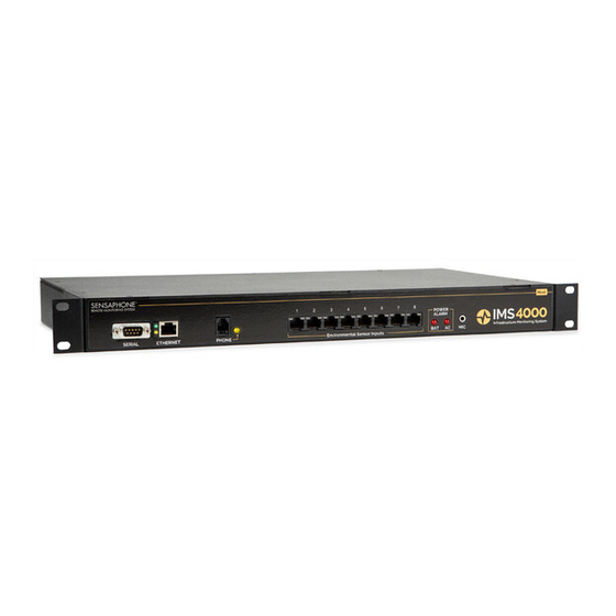
HOST INSTALLATION and CONFIGURATION Physical Description The IMS-4000 Host is housed in a 17"w x 1.75"h x 10"d enclosure, which is 1 EIA rack-mount space high. Front Panel Layout The front panel contains connections for eight sensor inputs, microphone input, Ethernet port, serial port, and status LEDs. -
Page 21: Phone Jack
Phone Jack Connect the IMS-4000’s Phone jack to a standard 2-wire analog phone line. The unit dials using touch-tones, with loop start only. The IMS-4000 will recognize ringer frequencies from 16 to 60 Hz and will operate with all standard analog telephone systems that accept tone dialing. -
Page 22: Ac Power And Battery Leds
AC Power and Battery LEDs The AC Power and Battery alarm status is indicated by two red LEDs. Their modes of operation are described below. Mode 1: No Alarm LED: Mode 2: Alarm detected but has not exceeded recognition time LED: FAST BLINK Mode 3: New Alarm exists and not yet acknowledged... -
Page 23: Operating Environment
Operating Environment Before you install the IMS-4000 Host be sure that your operating environment meets the physical requirements of the equipment. Operating Temperature: 32º –122º Fahrenheit (0º – 50º C) Humidity: Power: Rack Requirements: Tabletop requirements: Rack Mount Installation &A 5 –... -
Page 24: Tabletop Installation
The IMS-4000 Host can be installed on a tabletop or shelf. Follow the steps below: 1) Attach the four self-adhesive rubber feet to the four corners on the bottom of the IMS-4000. 2) Place the unit on a tabletop or shelf and connect the power cord into a 90-260VAC outlet. -
Page 25: Network Configuration
IMS-4000 installed in room A and you want to install a sensor in room B. If your existing cabling infrastructure has an unused cable path between room A and room B, then you simply use an RJ-45 interconnect cable to connect the IMS-4000 to the patch panel in room A, and an RJ-45 intercon- nect cable from the wall jack in room B to the sensor. -
Page 26: Default Gateway
Option 3 will allow you to set all pertinent network settings listed under Option 2. NOTE: You can remotely reconfigure the Host network settings using the IMS-4000 ConsoleView software if the Allow Remote Configuration option is set to Y. However, the Host must initially be configured via the serial port before any remote configuration is possible. - Page 27 Option 6 allows you to configure the RAS (Remote Access Server). This can be used to provide remote access to your network via a dial-up connection to the IMS-4000 Host. Note that there are serious security risks associated with enabling this feature. A sample of the RAS menu is shown...
-
Page 28: Local Configuration Definitions
Enter the IP address of the DNS server for your network. Enable Web: Setting this to “Y” will enable the web page feature of the IMS-4000. Set this to "N" if you do not want the unit to produce a web page. -
Page 29: Battery Maintenance
The IMS-4000 Host includes an internal UPS that automatically switches to battery backup in the event of an AC power failure. The battery in the IMS-4000 Host is a 12V 2.9AH gel cell. This bat- tery will keep the unit operating for approximately 3.5 hours when fully charged and under normal operating conditions. - Page 30 Attach the connector with the red wire to the positive terminal of the battery. Step 10) Attach the connector with the black wire to the negative terminal of the battery. Step 11) Replace the top IMS-4000 cover and secure with the screws. Step 12) Re-install in rack. Step 13) Re-attach the power cord.
-
Page 31: Ims Host Specifications
IMS Host Specifications Operating Specifications Communications Specifications Environmental Monitoring Number of Sensor Ports 8 Sensor Input Connector RJ-45 Temperature 32–122° F Humidity 5–90% RH non-condensing Power Supply 90–260VAC 50/60Hz Power Consumption 25 Watts Power Connection IEC 320 Dimensions 1.75"h x 9.5"d x 19"w Backup Battery 12V 2.9AH Sealed Gel Cell Backup Time 3.5 Hours Ethernet 10/100 Base-T, 10/100Mbps... -
Page 32: Node Installation & Configuration
NODE INSTALLATION & CONFIGURATION Physical Description The IMS-4000 Node is housed in a 9.6"w x 1.75"h x 7"d enclosure, which is 1 EIA rack-mount space high. Front Panel Layout The front panel contains connections for eight sensor inputs, microphone input, Ethernet port, serial port, and power LED. -
Page 33: On/Off Switch
Replacing batteries Parts Required Phillips Screwdriver Operating Environment Before you install the IMS-4000 Node be sure that your operating environment meets the physical requirements of the equipment. Operating Temperature: 32º –122º Fahrenheit (0º – 50º C) Humidity: Power: Rack Requirements:... -
Page 34: Battery Replacement
Battery Replacement The IMS-4000 Node uses one (1) 6V 3.4AH rechargeable battery (included) for backup power in the event that main power fails. The unit will constantly recharge the battery whenever the power switch is turned on and the unit is plugged into a power supply. -
Page 35: Tabletop Installation
Alarm contacts from external equipment All IMS-4000 sensors connect to the Node using standard RJ-45 cables. This makes it easy to con- nect sensors directly to the unit. Simply plug one end of the cable into the sensor and the other end into one of the sensor inputs on the Node. -
Page 36: Network Configuration
For example: Suppose you have an IMS-4000 Node installed in room A and you want to install a sensor in room B. If your existing cabling infrastructure has an unused cable path between room A and room B, then you simply use an RJ-45 interconnect cable to connect the IMS-4000 Node to the patch panel in room A, and an RJ-45 interconnect cable from the wall jack in room B to the sensor. -
Page 37: Local Configuration Definitions
Option 6 will logout without rebooting. Local Configuration Definitions Parent Host IP Address: This is the IP address of the IMS-4000 Host that this Node is associated with. Node IP Address: This is the IP address assigned to the IMS-4000 on your network. This address is provided by you or your network administrator. -
Page 38: Node Specifications
Node Specifications Operating Specifications Communications Specifications Environmental Monitoring Temperature 32–122° F Humidity 5–90% RH non-condensing Power Supply 120VAC 60Hz Power Consumption 10 Watts Dimensions 1.8"h x 7.0"d x 9.6"w Backup Battery (1) 6V 3.4AH sealed rechargeable Backup Time 3.5 Hours Ethernet 10/100 Base-T, 10/100Mbps RS-232 DB9, 9600bps, DTE Internal Monitoring... -
Page 39: Chapter 2: Ims-4000 Software
Enterprise, then Add Enterprise Group. See below: Right-click on the words IP Unknown below the enterprise name and select Set IP Address. Enter the IP address for your IMS-4000 Host and click OK. The software will prompt you for a username and password to log in. -
Page 40: Configure The Unit Properties For The Host And Node(S)
Most Alphanumeric pagers work best when set to 1200bps. The Host can synchronize its clock each night to a time server. To use this feature the IMS-4000 must have network access to a server which supports one of the following: Network Time Protocol - NTP (RFC-1035), Time Protocol - TP (RFC-868), or Daytime Protocol - DP (RFC-867). -
Page 41: Configure Ip Alarms
up alarm contact information, right-click on the profile name and select Add New Contact. You can have up to eight contacts per user. The User Profile screen is shown below: Configure IP Alarms Program the IP addresses for each network device you want to monitor. Expand the Host menu by clicking the plus sign next to the name of your host. -
Page 42: Software Installation And Hardware Requirements
Software Installation and Hardware Requirements This section describes how to install and configure the IMS-4000 ConsoleView Software for your enterprise. Hardware and Software Requirements Minimum Requirements: Intel Pentium processor or equivalent 30 MB of free disk space 32 MB of RAM (64 MB RAM recommended) -
Page 43: Starting The Ims-4000 Consoleview Software
Right-click on the words IP Unknown below the enterprise name and select Set IP Address. Enter the IP address for your IMS-4000 Host and click OK. The software will prompt you for a username and password to log in. For new units, the default username is admin and the default password is... -
Page 44: Connecting To A Host
The software will now attempt to connect to your IMS-4000 Host. A progress bar will show the software retrieving information from the Host. Default Username: admin adm4k... -
Page 45: Setting The Unit Properties For The Ims Host
Chapter 2: Software Setting the Unit Properties for the IMS Host To set the global properties of your IMS-4000, right-click on the Host name and select Unit Properties. On the System Info tab, enter the Unit Name, Description and Location. These param- eters will be used when sending alarms to identify the unit. -
Page 46: Adding A Node
The IMS-4000 can be programmed to synchronize its clock to a reference time server every night at midnight. To use this feature the IMS-4000 must have network access to a server which supports one of the following time code protocols:... -
Page 47: Deleting A Node
IP address. Setting the Unit Properties for the Node To set the Properties of your IMS-4000 Node, right-click on the Node name and select Node Properties. The Node Name will be copied from the node itself as programmed during the network configuration procedure. -
Page 48: Sample Application
In normal operation information is periodically passed between the Node and Host. This informa- tion mainly consists of current Input values and IP Alarm status. The amount of data transferred during this update is about 700 bytes. You can choose how often information is updated from the Node by selecting either periodic updates (Auto Send) or by selecting Update on a Percent Change basis. -
Page 49: Configuring Environmental Inputs
NOTE: If the Modify button is grey (inactive) then the unit either does not have the Allow Remote Configuration option set, or the unit’s firmware does not support this feature and requires upgrading. Enter the new network parameters and click OK. The Node will reboot and temporarily disconnect from the Host. - Page 50 In Use: This indicates that a valid sensor is plugged into the channel. Enabled: This indicates if the channel is currently enabled for alarm monitoring. If it is disabled, the IMS-4000 will not send alarm messages. A channel can be enabled or disabled based on a 7- day + holiday time schedule.
- Page 51 Custom Voice: Click the drop down arrow and select the custom voice message you would like assigned to this sensor/channel. Voice messages can be recorded on your PC and uploaded into the IMS-4000 on the Custom Voice Manager screen (See Recording and Uploading Voice Messages).
-
Page 52: Alarm Response Via The Powergate, Powergate2, Or Camera
Alarm Response via the PowerGate, PowerGate2, or Camera PowerGate When an alarm occurs, you can have PowerGate or PowerGate2 outlets automatically turn ON, turn OFF, or CYCLE power to a device. Cycling will switch an outlet OFF for 10 seconds and then switch it back ON. -
Page 53: High Sound Alarms
Contact Schedule. High Sound Alarms The IMS-4000 measures the sound level with the built-in microphone on the front panel. This can be useful in detecting audible alarms in close proximity to the unit. To detect alarms at a distance from the unit, you can plug an external condenser microphone into the mic jack. Note that the audible alarm must be more than just a periodic beep. -
Page 54: Environmental Input Alarm Logic
Trouble Alarms The IMS-4000 monitors the presence of all connected sensors to insure the reliability of the system. When a sensor is removed from a Host or Node for more than a minute, a trouble alarm is gener- ated. - Page 55 Chapter 2: Software configure the Templates, click the plus box next to the word Settings to expand the options under this heading. Next, expand the Input Templates. This will list all of the different sensor types. Figure 24: Template Types Right-click on each of the sensor names to bring up the individual Template programming screens.
-
Page 56: Configuring Ip Alarms
Enabled: This indicates if the IP Address is currently enabled for alarm monitoring. If it is disabled, the IMS-4000 will not send alarm messages. An IP Alarm can be enabled or disabled based on a 7-day + holiday time schedule. - Page 57 IMS-4000 on the Voice screen. Reset Time: This is the time allowed for an acknowledged alarm’s fault condition to be corrected before the IMS-4000 resets (reactivates) the alarm and begins the message delivery process all over again. The minimum reset time is 30 minutes.
-
Page 58: Alarm Logic
Once a successful response is received, the failure counter will reset. For example: If the ping Retries is set to 3, then the IMS-4000 must fail to ping/connect to the device 4 times in a row (initial attempt + 3 retries) to trip an alarm. If the device were to respond after the second attempt, then the failure counter would reset, thus requiring four subsequent successive failures to trip an alarm. -
Page 60: Input/Alarm Classes
Input/Alarm Classes Classes are used to associate environmental inputs and IP alarms with people. Each input sensor or IP address must be assigned to a Class. Each person or User Profile selects classes for which... -
Page 61: Configuring User Profiles And Contacts
When an alarm occurs the IMS-4000 will check the list of User Profiles to see who should be contacted. Users whose class list includes the class of the alarm will be contacted. Each user can have up to 8 contact destinations (phone numbers, e-mail addresses, …). -
Page 62: Permissions
Clicking the Permissions button will bring up the Permission screen. Permissions Each user profile has a programmable security level for each device (host/nodes) in the system. To set the Security Access level click the Permissions button. There are three access levels: Master System Administrator, Site Administrator, and User. -
Page 63: Classes
To configure profiles for Site Administrator or User security levels, select the appropriate Host or Node(s) and click the arrow to copy the Host/Node(s) into the appropriate list. The double arrow >> will copy all units to the list while the single arrow > will copy just the selected unit to the list. Checking the box “This user can connect remotely via modem”... -
Page 64: Deleting A Profile
The Contacts are the actual telephone numbers, e-mail addresses, pager numbers, etc… that the IMS-4000 will contact when an alarm occurs. You can have up to 8 Contacts per User Profile. Each Contact can have its own Schedule so that you can have certain Contacts be Enabled during daytime hours and others Enabled during nighttime hours. -
Page 65: Voice Calls
For most voice calls you can simply enter the telephone number of the person you want called. Consider the location of the IMS-4000 Host when entering the number. If an area code is required to call from the Host to your telephone, be sure to include it. -
Page 66: Fax Calls
Once the alarm message has been delivered, the IMS will stop calling this contact. This selection is useful for insuring that a record of an alarm is sent. When this option is checked, the IMS-4000 will always send an alarm message to this contact. -
Page 67: Saving And Loading Programming
Saving and Loading Programming The programming in your IMS-4000 can be saved to a file. This gives you the ability to back up your programming or copy the same programming to another IMS-4000 unit. Note that the file you save will not include custom voice files or settings entered through the serial port (network param- eters, web settings, two-way e-mail, RAS, etc.). -
Page 68: Recording Voice Messages
See the following screen. Figure 38: Sound Specifications screen Next, save this recording format by typing “IMS-4000” in the Name field and click Save As. Click OK on each screen until you get back to the Sound Recorder main screen. -
Page 69: Holiday Setup
IMS-4000 and will appear in the list. The window to the right displays all of the voice message file names stored in the IMS-4000. To change the file name of a voice message click Rename. Enter a new file name and click OK. -
Page 70: Alarm Message Pop-Ups
Alarm Message Pop-Ups While online with one or more IMS-4000 units through the ConsoleView Software, you can have an alarm message pop up on your computer screen whenever an alarm occurs. This could be an environmental or IP alarm on any Host or Node. You can configure this feature to display a general message indicating the Unit and Channel names, or you can associate a custom message with each input. -
Page 71: Enabling Custom Pop-Up Messages
Chapter 2: Software Enabling Custom Pop-Up Messages To have custom messages pop up, you must enable this feature. Select Options from the main menu. Click in the box labeled Include Custom Message with Alarm Pop-Ups. Next, you must select where your custom messages will be stored (see below). Setting Pop-Up Text Location When using custom pop-up messages you must specify where these messages will be located. -
Page 72: Audible Alarm Notification
Return Address programmed. These are the minimum programming requirements to send e- mail. If you have at least these two items programmed and the IMS-4000 is unable to deliver the message, then you will get the message “SMTP Server not Responding,” which essentially means... -
Page 73: Two Way E-Mail
IMS-4000. A set of commands is available that can be sent to a 4000, within an e-mail, that will cause the 4000 to reply back to the sending e-mail address. Commands are available to inquire status, perform network ping and IP trace-route, and control outlets on a PowerGate. -
Page 74: Requesting A Trace Route
Requesting a Trace Route To request an IP trace-route, send an e-mail message to your IMS-4000 Host with the following information: To: <e-mail address of your IMS-4000> Subject: ims4000 username: <valid profile username> email: <your e-mail address> command: traceroute xxx.xxx.xxx.xxx... -
Page 75: Requesting Help
Capture Image. The first step is to get the camera running on your network. This process is independent of the IMS-4000. Follow the instructions included with the camera to get it set up. Once the camera is 241Q... - Page 76 IMS-4000 ConsoleView Software. Cameras are added to the IMS by expanding the Settings menu and right-clicking on the word Cameras. Choose Add Camera. This will bring up the Camera Setup screen (see below). Enter the IP address, port number, and security settings (if required) of the camera according to how it has been configured on your network.
-
Page 77: Web Page
Web Page The IMS-4000 will produce a web page which includes: • The status of all Environmental Inputs and IP Alarms. • The ability to program most parameters. • Links to view logged data for each Input and IP alarm. -
Page 78: Updating The Web Page
Figure 51: Web Page Refresh Enabled Remote Web Page The IMS-4000 can send a copy of its web page to another web server via FTP (File Transfer Protocol), so that the web page can be viewed on another network (for example, on the Internet). -
Page 79: Viewing The Remote Web Page
Viewing the Remote Web Page To view the remote web page that the IMS-4000 uploaded, you need to know its web address. This address corresponds to the Server name, plus the directory, plus the file name of the web page. It will look something like this: http://www.mycompany.com/jwilson/ims4k.html... -
Page 80: History
The eventlog history is useful when you want to review the historical events monitored and performed by the IMS-4000. When a user goes online, information for both the datalog and eventlog history is automatically retrieved and stored in a database on a user-specified hard disk. -
Page 81: Datalog History
Chapter 2: Software Datalog History The IMS-4000 can log up to 62,500 samples of environmental and IP Alarm history. When the log fills, it will overwrite the oldest data first. Environmental data will display the actual value, while IP Alarm data will display either Normal, Timed Out, or IP Down. All stored history is logged at the same interval as programmed on the History programming screen. -
Page 82: Graphing
To begin, run the HistoryView program by right-clicking on History in the menu tree and select HistoryView, or from the main menu select File, then HistoryView. The first screen will prompt you to select an IMS Host. Click in the box next the Host you want to Query. The program will then load the associated nodes and input names. -
Page 83: Printing Data
Printing Data You can print the data viewed in the grid by clicking the Print button. Printing defaults to an Arial 5 pt. font in order to fit one line of data across one line of an 8.5" x 11" sheet of paper printed in landscape mode. -
Page 84: Manually Forcing History Downloads
From time to time Firmware updates will become available to add features or improve the perfor- mance of your IMS-4000. Most Firmware updates will be included as part of a complete IMS- 4000 installation upgrade. Check the IMS-4000 website (www.sensaphone.com/support-4000.html) for the latest information on updates. -
Page 85: Chapter 3: Operation
This chapter explains how the IMS-4000 operates. Alarm Delivery and Acknowledgment The IMS-4000 can be programmed to contact specific users when an alarm occurs. A user may be contacted depending on whether the alarm has already been acknowledged by another user, or regardless of acknowledgement by other users. -
Page 86: Alarm Delivery Logic
5) By SNMP Management software. 6) By the IMS-4000 itself. If there are no Until Acknowledge contacts in the call list or if the maximum number of calling rounds has been exhausted, the IMS-4000 will self-acknowledge the alarm. Alarm Delivery Logic When an alarm occurs, the IMS-4000 will check for Class matches between the input or IP alarm and the User Profiles. -
Page 87: Sample Fax Message
Thursday 28 March 2002, 10:24:32 AM EST Voice Status Report and Touch-Tone Commands The IMS-4000 is capable of delivering a spoken status report when called via telephone. The status report can provide information on both environmental conditions and IP alarms. In addition, you can ping devices over the telephone and switch PowerGate outlets. -
Page 88: Sample Status Report
User has no Environmental sensors in his class, then these will be skipped. Voice Alarm Dialout The IMS-4000 can call and deliver an alarm message in spoken English. After dialing, the unit will begin speaking “IMS-4000 Alarm Message, Press any key to continue.” If the unit receives a touch-tone, it will recite the alarm message. -
Page 89: Performing An Ip Ping Via Telephone
Performing an IP Ping via Telephone The IMS-4000 allows you to perform an IP Ping during a voice call-in to the Host. After dialing the unit, press a touch-tone after the beep. The unit will request your User Code. Next, listen to the menu choices. -
Page 90: Windows 2000
For the Network Connection Type choose Dial-up to Private Network. Enter the telephone number of your IMS unit and assign a name to the connection (“IMS-4000,” for example). When prompted to enter your Username and Password be sure to enter information which matches a Profile Username and Password in your IMS-4000. -
Page 91: Chapter 4: Snmp (Simple Network Management Protocol)
The IMS-4000 Host contains an SNMP agent that supports all three current versions of SNMP (v1, V2c, and V3), over both UDP and TCP transports. Read and write access to most of the IMS-4000 parameters is provided along with the ability to send traps when alarms occur. A complete SNMPv1 MIB is provided on the IMS-4000 CD. - Page 92 Object Identifier (OID), which usually has a name in the form of numbers separated by periods (“.”), like this: .1.3.6.1.x.x.xxxx.x.x.x.x... OIDs for all MIB variables can be determined by browsing the MIB. Below are some examples of the more common OIDs in the IMS-4000: Name: .iso.org.dod.internet.private.enterprises.sensaphone Sensaphone OID: .1.3.6.1.4.1.8338 Host Environmental Input Values: .1.3.6.1.4.1.8338.1.1.1.1.8.1.1.7.(input number)
-
Page 93: Chapter 5: Powergate
Chapter 5: PowerGate Physical Description The IMS-4000 PowerGate is housed in a 17"w x 1.75"h x 10"d enclosure, which is 1 EIA rack- mount space high. Front Panel Layout The front panel contains a 15 Amp breaker, Output LEDs, the serial port and power indicator. See... -
Page 94: Parts Required
Parts Required Phillips Screwdriver Operating Environment Before you install the IMS-4301 PowerGate be sure that your operating environment meets the physical requirements of the equipment. Operating Temperature: 32º –122º Fahrenheit (0º – 50º C) — Humidity: Power: Rack Requirements: Tabletop requirements: Rack Mount Installation The IMS-4301 PowerGate can be rack mounted using the included rack mount brackets. -
Page 95: Tabletop Installation
Connection to IMS-4000 Host or Node The PowerGate connects to an IMS-4000 Host or Node using the 9-pin null modem cable (includ- ed). Connect the cable to the RS-232 port on the PowerGate and connect the other end to the RS- 232 port on the Host or Node. -
Page 96: Powergate Setup Via The Ims Consoleview Software
Each outlet provides 115VAC 60Hz. To ensure that the maximum power will be available, be sure to plug the PowerGate itself into a circuit which can supply at least 15 Amps. The total of all devic- es connected to the PowerGate cannot exceed 15Amps. PowerGate Setup via the IMS ConsoleView Software The PowerGate will automatically be recognized by the IMS Host or Node. -
Page 97: Switching Outlets Using The Ims Consoleview Software
Alarms in the IMS-4000 Software Configuration Manual for details. Switching Outlets via Telephone The IMS-4000 allows you to switch PowerGate outlets using a touch-tone telephone. To do this simply call the unit and enter the voice menu system. You must have a valid user code and the appropriate permissions to execute this command. -
Page 98: Ims Powergate Specifications
IMS PowerGate Specifications Operating Specifications Power Supply Current Consumption Over-Current Protection Temperature 32–122° F Humidity 5–90% RH non-condensing 120VAC 60Hz 100mA + output load 15A Breaker Dimensions 1.8"h x 10.0"d x 17.3"w... -
Page 99: Chapter 6: Powergate2
Chapter 6: PowerGate2 Physical Description The IMS-4000 PowerGate2 is housed in a 17.5"w x 1.75"h x 12.3"d enclosure, which is 1 EIA rack-mount space high. Front Panel Layout The front panel contains eight power inputs corresponding to the eight outlets on the rear, eight 15 Amp breakers, power LEDs, a serial port and one power indicator LED. -
Page 100: Installation
Installation This section provides information on: n Operating environment n Rack, wall, and tabletop installation Parts Required Phillips Screwdriver *For additional right-angle power input cables, order part # IMS-4413. Operating Environment Before you install the IMS-4302 PowerGate2 be sure that your operating environment meets the physical requirements of the equipment. -
Page 101: Wall Mount Installation
Wall Mount Installation The IMS-4302 PowerGate2 can be wall mounted using the optional wall mount brackets. Follow the steps below: 1) Attach the optional wall mount brackets to the sides of the IMS-4302 using the eight black #6-32 screws. A Phillips screwdriver will be required. (Order part # IMS-4501 Universal Wall Mount Kit) 2) Attach the unit to the wall using two screws per side. -
Page 102: Operation
Figure 6: PowerGate2 to Node connection... -
Page 103: Latched Power To Outlets
Chapter 6: PowerGate2 unit from bending down (See the figure below). Too much weight in the rear may cause permanent damage to the enclosure. Figure 8: Cable Support Each outlet will pass the connected power through from the corresponding power input. Note that the PowerGate2 is designed for 120VAC circuits only. -
Page 104: Switching Outlets Using The Ims Consoleview Software
Figure 11: Switching Outlets Automatic Outlet Switching The IMS-4000 allows you to program an Alarm Response whenever an environmental or IP Alarm occurs. An Alarm Response is an action that occurs automatically whenever an alarm occurs. Using the PowerGate2 you can automatically turn On, Off, or Cycle equipment whenever an... -
Page 105: Switching Outlets Via Telephone
Environmental or IP alarm occurs. Up to eight actions can be applied for each alarm response. The PowerGate2 will perform all automated switching simultaneously. See Configuring Environmental Inputs and Configuring IP Alarms... - Page 106 IMS-4000 Manual...
-
Page 107: Chapter 7: Ims-4000 Sensors
" hex key Cabling The temperature sensor connects to the IMS-4000 Host or Node via an RJ-45 cable (e.g. CAT5 cable). The connection from the sensor to the Host or Node can utilize your existing network wir- ing infrastructure. For example, the sensor may be installed in another room or another floor. -
Page 108: Hidden Cable Surface Installation
using the appropriate screws. Secure the sensor cover by turning the two hex screws on the bottom of the cover counterclockwise. Figure 1: 4810 with Cable exiting through back of enclosure Hidden cable surface installation Bring the RJ-45 cable through the wall at the mounting location. Remove the sensor cover by turn- ing the two hex screws on the bottom of the sensor housing clockwise. -
Page 109: Configuration
Figure 2: 4810 with Cable exiting out enclosure bottom Configuration All IMS Solution sensors are auto-configured when you plug them into the Host or Node. When a new sensor is plugged into the Host or Node, the configuration is set to the factory default via the Sensor Template. -
Page 110: Sensor Template (Factory Default)
Sensor Template (factory default) Input Name: Low Temperature Limit: High Temperature Limit: Recognition Time: Reset Time: Data Logging: Input Class: Specifications Humidity: Sensor type: Accuracy: Connector: Temperature 50º F 85º F 60 Seconds 0 Seconds Active Voice: temperature.wav Temperature Range: 5–122 degrees F (-15 to 50 degrees C) 5–90 %RH solid state ic... -
Page 111: Ims-4811 Room Temperature Sensor With Display (Fahrenheit)
" hex key Cabling The temperature sensor connects to the IMS-4000 Host or Node via an RJ-45 cable (e.g. CAT5 cable). The connection from the sensor to the Host or Node can utilize your existing network wiring infrastructure. For example, the sensor may be installed in another room or another floor. Connect the sensor to your structured wiring network via an RJ-45 jack. -
Page 112: Hidden Cable Surface Installation
Figure 1: 4811 with Cable exiting through back of enclosure Hidden cable surface installation Bring the RJ-45 cable through the wall at the mounting location. Remove the sensor cover by turn- ing the two hex screws on the bottom of the sensor housing clockwise. Bring the cable through the back of the sensor and hold the sensor housing against the wall. -
Page 113: Configuration
Configuration All IMS Solution sensors are auto-configured when you plug them into the Host or Node. When a new sensor is plugged into the Host or Node, the configuration is set to the factory default via the Sensor Template. If you have modified these templates, the configuration will be set to the modi- fied configuration. -
Page 114: Ims-4812 Mini-Temperature Sensor (Fahrenheit)
The Mini-Temperature Sensor comes with an attached 7' cable with an RJ-45 plug on the end. If the sensor is close to the IMS-4000 Host or Node, you can plug the sensor directly to an IMS environ- mental input. If the cable is too short you can use the included RJ-45 adaptor and a longer patch cable to extend the length. -
Page 115: Sensor Template (Factory Default)
Sensor Template (factory default) Input Name: Low Temperature Limit: High Temperature Limit: Recognition Time: Reset Time: Data Logging: Input Class: Specifications Humidity: Sensor type: Accuracy: Connector: Housing: Housing dimensions: Temperature 50º F 85º F 60 Seconds 0 Seconds Active Voice: temperature.wav Temperature Range:... -
Page 116: Ims-4813 Room Temperature Sensor With Display (Celsius)
" hex key Cabling The IMS-4813 temperature sensor connects to the IMS-4000 Host or Node via an RJ-45 cable (e.g. CAT5 cable). The connection from the sensor to the Host or Node can utilize your existing network wiring infrastructure. For example, the sensor may be installed in another room or another floor. -
Page 117: Hidden Cable Surface Installation
Figure 1: 4813 with Cable exiting through back of enclosure Hidden cable surface installation Bring the RJ-45 cable through the wall at the mounting location. Remove the sensor cover by turn- ing the two hex screws on the bottom of the sensor housing clockwise. Bring the cable through the back of the sensor and hold the sensor housing against the wall. -
Page 118: Configuration
Configuration All IMS Solution sensors are auto-configured when you plug them into the Host or Node. When a new sensor is plugged into the Host or Node, the configuration is set to the factory default via the Sensor Template. If you have modified these templates, the configuration will be set to the modi- fied configuration. -
Page 119: Ims-4820 Room Humidity Sensor
" hex key Cabling The humidity sensor connects to the IMS-4000 Host or Node via an RJ-45 cable (e.g. CAT5 cable). The connection from the sensor to the Host or Node can utilize your existing network wiring infra- structure. For example, the sensor may be installed in another room or another floor. Connect the sensor to your structured wiring network via an RJ-45 jack. -
Page 120: Hidden Cable Surface Installation
Figure 1: 4820 with Cable exiting through back of enclosure Hidden cable surface installation Bring the RJ-45 cable through the wall at the mounting location. Remove the sensor cover by turn- ing the two hex screws on the bottom of the sensor housing clockwise. Bring the cable through the back of the sensor and hold the sensor housing against the wall. -
Page 121: Configuration
Configuration All IMS Solution sensors are auto-configured when you plug them into the Host or Node. When a new sensor is plugged into the Host or Node, the configuration is set to the factory default via the Sensor Template. If you have modified these templates, the configuration will be set to the modi- fied configuration. -
Page 122: Ims-4821 Room Humidity Sensor With Display
(1) 1/16" hex key Cabling The humidity sensor connects to the IMS-4000 Host or Node via an RJ-45 cable (e.g. CAT5 cable). The connection from the sensor to the Host or Node can utilize your existing network wiring infra- structure. For example, the sensor may be installed in another room or another floor. Connect the sensor to your structured wiring network via an RJ-45 jack. -
Page 123: Hidden Cable Surface Installation
Figure 1: 4821 with Cable exiting through back of enclosure Hidden cable surface installation Bring the RJ-45 cable through the wall at the mounting location. Remove the sensor cover by turn- ing the two hex screws on the bottom of the sensor housing clockwise. Bring the cable through the back of the sensor and hold the sensor housing against the wall. -
Page 124: Configuration
Configuration All IMS Solution sensors are auto-configured when you plug them into the Host or Node. When a new sensor is plugged into the Host or Node, the configuration is set to the factory default via the Sensor Template. If you have modified these templates, the configuration will be set to the modi- fied configuration. -
Page 125: Ims-4830 Water Detection Sensor
(4) Rubber feet Cabling The water detection sensor connects to the IMS-4000 Host or Node via an RJ-45 cable (e.g. CAT5 cable). The connection from the sensor to the Host or Node can utilize your existing network wir- ing infrastructure. For example, the sensor may be installed in another room or another floor. -
Page 126: Cascading Water Sensors
IMS-4000 Manual Cascading Water Sensors You can cascade up to three Water Detection Sensors from a single IMS input channel. This is use- ful if there is a large distance between each sensor and you donʼt want to use up additional IMS inputs for individual sensors. -
Page 127: Sensor Template (Factory Default)
the sensor is plugged in again, or the connection is re-established, configuration data remains unchanged and the sensor returns to normal operating condition. Caution: Removing a sensor for less than 60 seconds does not produce a trouble alarm. Removing or unplugging a sensor for more than 60 seconds or plugging in a different sensor at any time will cause a trouble alarm. -
Page 128: Ims-4840 External Power Sensor
(4) Rubber feet Cabling The Power Sensor connects to the IMS-4000 Host or Node via an RJ-45 cable (e.g. CAT5 cable). The connection from the sensor to the Host or Node can utilize your existing network wiring infra- structure. For example, the sensor may be installed in another room or another floor. Connect the sensor to your structured wiring network via an RJ-45 jack. -
Page 129: Mounting
Mounting The sensor can be mounted to a wall or lie flat on the floor. To mount the sensor to a wall, install the two drywall anchors (if necessary) and attach the Power Sensor using the two #6 tapping screws. When installing the sensor on the floor, attach the four rubber feet to the bottom of the enclosure. -
Page 130: Sensor Template (Factory Default)
Sensor Template (factory default) Input Name: Low Limit: High Limit: Recognition Time: Reset Time: Data Logging: Input Class: Specifications Accuracy: Power Connection: IMS Connection: Power 90VAC 130VAC 60 Seconds 0 Seconds Active Voice: power default.wav Power Range: 0–250 VAC, 50/60 Hz ±... -
Page 131: Ims-4850 Dry Contact Bridge
Cabling The Dry Contact Bridge connects to the IMS-4000 Host or Node via an RJ-45 cable (e.g. CAT5 cable). The connection from the sensor to the Host or Node can utilize your existing network wiring infrastructure. For example, the sensor may be installed in another room or another floor. -
Page 132: Mounting
Caution: The IMS sensors are not TCP/IP devices and therefore should not be connected directly to any wiring infrastructure that is connected to network equipment such as a hub, router, or switch. Sensors use RJ-45 plugs and cables similar to those used with Ethernet devices. -
Page 133: Sensor Template (Factory Default)
Sensor Template (factory default) Input Name: Recognition Time: Reset Time: Data Logging: Input Class: Specifications Source/Sense Voltage: Source/Sense Current: IMS Connection: Operating Temperature Range: Housing: Contact Bridge 3 Seconds 0 Seconds Active Voice: dry contact.wav Other Input: Normally Open or Normally Closed dry contact 14VDC 10mA RJ-45... -
Page 134: Ims-4851 4-20Ma Bridge
Figure 1: 4–20mA transducer wiring to IMS-4851 Terminal Block Cabling The 4-20mA Bridge connects to the IMS-4000 Host or Node via an RJ-45 cable (e.g. CAT5 cable). The connection from the sensor to the Host or Node can utilize your existing network wiring infra- structure. -
Page 135: Mounting
Chapter 7: IMS-4000 Sensors F i g u r e 3 : M o u n t i n g t h e s e n s o r F gure 2 Mou t ngThe 4-20 A Bridge can be mounted to a wall or lie flat on the floor. To mount it to a wall, install... -
Page 136: Host And Node Firmware Requirements
The 4-20mA Bridge requires the following firmware versions in the Host and Node(s) for sensor compatibility: IMS-4000 Host • Input board firmware chip version xx.xx.xx.103 or higher NOTE: Input board firmware is NOT flash upgradeable. A new firmware chip must be installed. -
Page 137: Ims-4860 Door Switch
Introduction The IMS-4000 Door Switch with bridge enables your IMS-4000 to detect if any unauthorized entry or intru- sion has occurred. The bridge may be mounted either on a wall or rest on the floor. The switch is mounted to doors or windows you wish to monitor. -
Page 138: Mounting The Bridge
The choice depends on your specific application. Cabling The Door Switch connects to the IMS-4000 Host or Node via an RJ-45 cable (e.g. CAT5 cable) from the bridge. The connection from the bridge to Host or Node can utilize your existing network wiring infrastructure. -
Page 139: Specifications
Specifications Bridge: Source/Sense Voltage: Source/Sense Current: Cable/Connector: Operating Temperature Range: Dimesnsions: Door Switch: Input: Normally Open or Normally Closed dry contact 14VDC 10mA 7' cable with RJ-45 plug 32–122 deg F (0-50 degC) Housing: Black plastic 2.13" x 0.6" x 1.38" Normality: Normally Closed Dimensions:... -
Page 140: Ims-4861 Passive Infrared Detection Sensor
The Passive Infrared Detection Sensor comes with an attached 7' cable with an RJ-45 plug on the end. If the sensor is close to the IMS-4000 Host or Node, you can plug the sensor directly to an IMS environmental input. If the cable is too short you can use the included RJ-45 adaptor and a longer patch cable to extend the length. -
Page 141: Configuration
Ceiling Mounting Run all cable wiring to the sensor through either the Wire Access Slot (wall mounted), or the Wire Access Hole (ceiling mounted). The sensor can also be attached directly to a wall or corner without the bracket. Knockout holes for direct mounting can be accessed by opening the sensor body (see instructions below), taking out the PC board by removing the single screw that holds it in place, and then knocking out the appro- priate four (4) holes: flat holes for direct mounting, or side (angled) holes for corner-mounting. -
Page 142: Sensor Template (Factory Default)
PULSE/AUTO: Pulse Count Jumper Jumper in position 1 (to the right): Jumper setting for a stable environment without air drafts. Jumper in position AUTO (to the left): Setting for a harsh environment. Figure 2: Sensitivity adjustment and jumper locations Sensor Template (factory default) Input Name: Recognition Time: Reset Time:... -
Page 143: Ims-4862 Smoke Detector Sensor
7' cable with an RJ-45 plug on the end. If the sensor is close to the IMS-4000 Host or Node, you can plug the sensor directly to an IMS environmental input. If the cable is too short you can use the included RJ-45 adaptor and a longer patch cable to extend the length. -
Page 144: Sensor Template (Factory Default)
Sensor Template (factory default) Input Name: Recognition Time: Reset Time: Data Logging: Input Class: Specifications Sensitivity: Contact Rating: Heat sensor rating: Operating voltage: Maximum ambient temperature: Power-up time: Housing: Housing dimensions: Smoke Detector 10 Seconds 0 Seconds Active Voice: smoke detector.wav Smoke 2.0 ±... -
Page 145: Technical Support For The Ims-4000 Sensors
Technical Support for the IMS-4000 Sensors For questions about installing any of these sensors, please contact your local IMS Solution Reseller or VAR or contact the manufacturer directly at: Phonetics, Inc. 901 Tryens Road Aston, PA 19014 www.ims-4000.com Tel: 610.558.2700 Fax: 610.558.0222... - Page 146 IMS-4000 Manual...
-
Page 147: Appendix A: Weekly Testing Procedure
4) If you are using your IMS-4000 to listen for a smoke alarm, then be sure to test the smoke alarm to make sure that the IMS-4000 picks up the audible signal and triggers a high-sound-level alarm. - Page 148 IMS-4000 Manual...
-
Page 149: Appendix B: Troubleshooting
The IMS-4000’s Host or Node’s network settings may be incorrect. Verify the IP address, Gateway, DNS, and Subnet mask settings. l There may be a network IP address conflict. The IMS-4000 Host or Node’s IP address may be the same as another device on your network. - Page 150 Yes. Why won’t my IMS-4000 Host dial out? l Check that you have a Touch-Tone telephone line. The IMS-4000 Host will not be able to dial out if it’s on a Pulse telephone line. l The Contact telephone number may be incorrectly programmed. Verify the telephone numbers. Is a ‘1 +area code’...
-
Page 151: Appendix C: Ims-4000 Accessories
Appendix C: IMS-4000 Accessories The accessories listed below are available from Phonetics, Inc. and our authorized distributors. Other dry contact sensors, designed for more specialized applications, may also be used. Commercial/industrial elec- trical supply houses can provide devices to monitor virtually any condition. For further information, con- tact Sensaphone Customer Service at 610.558.2700. - Page 152 IMS-4840 IMS-4850 IMS-4851 IMS-4860 IMS-4861 IMS-4862 IMS-4000 Power Sensor IMS-4000 Dry Contact Bridge IMS-4000 4–20mA Bridge IMS-4000 Door Switch IMS-4000 Passive Infrared Motion Detector w/7' RJ-45 Cable IMS-4000 Smoke Detector w/7' RJ-45 Cable...
-
Page 153: Appendix D: License Agreement For Sensaphone Ims-4000Consoleview Software
Sensaphone IMS-4000 monitoring hardware. You may make copies of the software and transfer your rights under this agreement, provided that each recipient of the software also agrees to the terms of this agreement. - Page 154 IMS-4000 Manual incorporated into the Software), and any copies of the Software are owned by Sensaphone (or one or more of its licensors). The Software is protected by copyright laws and international treaty provisions. Therefore, you must treat the Software like any other copyrighted material except that you may make copies of the Software, subject to the limitations set forth herein.
- Page 155 Appendix D: ConsoleView License Agreement INABILITY TO USE SENSAPHONE’S SOFTWARE, OR FROM THE FAILURE OF SENSAPHONE’S SYSTEM TO REPORT A GIVEN EVENT OR CONDITION, WHETHER OR NOT CAUSED BY SENSAPHONE’S NEGLIGENCE. V. WITHOUT WAIVING ANY PROVISION IN THIS LICENSE AGREEMENT, IF A CIRCUMSTANCE ARISES WHERE SENSAPHONE AND/OR ITS LICENSORS ARE FOUND TO BE LIABLE FOR ANY LOSS OR DAMAGE ARISING OUT OF MISTAKES, NEGLIGENCE, OMISSIONS, INTERRUPTIONS, DELAYS, ERRORS OR DEFECTS IN THE SOFTWARE SUBJECT TO THIS AGREEMENT, THEN SUCH LIABILITY...
- Page 156 IMS-4000 Manual Deemed acceptance and applicable law The installation or use of the Software is deemed acceptance of the terms and conditions contained in the License Agreement. This License Agreement shall be effective and binding upon Sensaphone and you, the end user, upon installation or use of the Software.
-
Page 157: Appendix E: Returning An Ims Unit For Repair
Appendix E: Returning an IMS Unit for In the event that any of your Sensaphone IMS-4000 units does not function properly, we suggest that you do the following: 1) Record your observations regarding the individual unit’s malfunction. 2) Call the Technical Service Department at 610.558.2700 prior to sending the unit to Phonetics, Inc. - Page 158 IMS-4000 Manual...
-
Page 159: Test Log
Test Log... - Page 160 IMS-4000 Host Installation Manual...
-
Page 161: Index
Index Accessories 151–152 Alarm Audible Notification 72 Delivery & Acknowledgment 85–87 Acknowledgment 85–86 Alarm Delivery Logic 86–87 Sample Alarm Messages 86–87 Environmental Input Alarm Logic 54 High Sound 53 Message Pop-Ups 70–72 Activating 70 Editing 71 Enabling Custom Messages 71 Setting Pop-Up Text Location 71 Response Camera Snapshots on Alarm 52–53... -
Page 162: Connecting Sensors
FCC Requirements iv Firmware Updating 84 History 79–84 Archiving the Database 83 Copying to the Clipboard 83 Datalog History 80–81 Deleting Data 83 Exporting Data 82–83 Graphing 82 Manually Forcing Downloads 83–84 Printing Data 82 Querying the History Database 81–82 QuickView 81 Viewing (HistoryView) 81–82 Holiday Setup 69... -
Page 163: Operation
Network Configuration 36–37 Rear Panel 33 Setting the Unit Properties 47–48 Sample Application 48 Specifications 38 PowerGate Connection to IMS-4000 Host or Node 95 Front Panel Layout 93 LEDs 93 Installation 93–95 Rack Mount Installation 94 Tabletop Installation 95 Wall Mount Installation 94–95 Operation 95–98... - Page 164 Realtime Strip Chart 53 Sensors 107–146 IMS-4810 Room Temperature Sensor 107–110 Cabling 107 Configuration 109 Mounting 107–109 Specifications & Defaults 110 IMS-4811 Room Temperature Sensor with display (F) 111–113 Cabling 111 Configuration 113 Mounting 111–112 Specifications & Defaults 113 IMS-4812 Mini-Temperature Sensor (F) 114–115 Cabling 114 Configuration 114 Mounting 114...
- Page 165 Video Camera Configuring 75–76 Voice Messages Recording 68–69 Recording & Uploading 67–69 Record & Assign 41 Voice Status Report & Touch-Tone Commands 87–89 Call-in Alarm Acknowledgment 89 Communicating with your IMS-4000 90 Remote Login via Dialup 89–90 Windows 2000 90...
- Page 166 Windows XP 90 User Specific Reports 87 Sample Status Report 88 Voice Alarm Dialout 88–89 Performing an IP Ping via Telephone 89 Warranty vii–viii Web Page 77–79 Graphs 77–78 Remote Web Page 78–79 Updating 78 Weekly Testing Procedure 147...
Need help?
Do you have a question about the Sensaphone IMS-4000 and is the answer not in the manual?
Questions and answers