Table of Contents
Advertisement
Quick Links
Advertisement
Table of Contents

Related Manuals for LifeGear Orbi trac 28320


Summary of Contents for LifeGear Orbi trac 28320
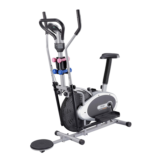
- Page 1 Orbi trac ITEM NO.: 28320 OWNER’S MANUAL IMPORTANT: Read all instructions carefully before using this product. Retain this owner’s manual for future reference. The specifications of this product may vary from this photo and are subject to change without prior notice. 2021, April...
-
Page 2: Table Of Contents
TABLE OF CONTENTS WARRANTY ------------------------------------------------------------------------------- 2 IMPORTANT SAFETY INSTRUCTIONS ------------------------------------------- 3 PARTS LIST ------------------------------------------------------------------------------- 4 HARDWARE LIST ----------------------------------------------------------------------- 6 TOOLS -------------------------------------------------------------------------------------- 8 EXPLODED VIEW ----------------------------------------------------------------------- 9 ASSEMBLY INSTRUCTIONS --------------------------------------------------------- 10 OPERATING THE COMPUTER ------------------------------------------------------ 32 ADJUSTMENTS -------------------------------------------------------------------------- 34 USING THE WAIST TWISTING DISC ---------------------------------------------- 35 MAINTENANCE -------------------------------------------------------------------------- 36 TROUBLESHOOTING ------------------------------------------------------------------ 36 WARM UP AND COOL DOWN ROUTINE ----------------------------------------- 37... -
Page 3: Warranty
ONE YEAR LIMITED WARRANTY LifeGear Inc. warrants to the original purchaser that this product is free from defects in material and workmanship when used for the purpose intended, under the conditions that it has been installed and operated in accordance with LifeGear's Owner's Manual. LifeGear's obligation under this warranty is limited to replacing or repairing free of charge, any parts which may prove to be defective under normal home use. -
Page 4: Important Safety Instructions
IMPORTANT SAFETY INSTRUCTIONS Basic precautions should always be followed, including the following important safety instructions when using this equipment. Read all instructions before using this equipment. Read all instructions and follow it carefully before using this equipment. Make sure the equipment is properly assembled and tightened before use. -
Page 5: Parts List
PARTS LIST Description Qty No. Description Round End Cap Ø25x1.5 8 024 Chain 1/4" Handrail Arm Foam Grip 2 025 Hexagon Head Cap Bolt M10x55 Ø32xØ23x280 Powder Metal Bushing Right Handrail Arm Ø25x1.8 1 026 Ø14xØ10x10 Square End Cap (□30x30) Left Handrail Arm Ø25x1.8 1 027 Plastic Bushing Ø28.5xØ25.4x84... - Page 6 PARTS LIST Description Qty No. Description Curve Washer Ø10xØ25x1.5 4 070 Seat Cushion DD-PU981T Carriage Pan Head Cap Bolt 4 071 Seat Post M10x57 Front Stabilizer Ø50x1.5x470 1 072 Seat Post Bellows Seat Height Adjustment Knob Rear Stabilizer Ø50x1.5x470 1 073 Washer Ø40xØ24x3 1 074 Seat Post Plastic Bushing...
-
Page 7: Hardware List
PARTS LIST Description Qty No. Description Handlebar Decorate Cover B 1 099 Washer Ø5xØ9x0.8 Hexagon Socket Pan Head Cap 2 100 Washer Ø30xØ10.5x2.5 Bolt M10x30 Hexagon Socket Pan Head Cap 1 101 Lock Pin Ø8x65 Bolt M8x57 Waist Twisting Disk Support Waist Twisting Disk Ø256 1 102 Frame... - Page 8 (46) Bolt for left Crank (43) Nylon Nut for left Ø16x89xL23 Crank B0.5x20 1 PC 1 PC (11) Wave Washer (39) Spring Washer Ø28xØ16x1.0t Ø20xØ13x2 1 PC 1 PC (47) Cap Nut M10 4 PCS (48) Curve Washer (32) Nut Cap S13 Ø10xØ25x1.5 2 PCS 4 PCS...
-
Page 9: Tools
TOOLS Allen Wrench 6mm Allen Wrench 8mm 2 PCS 1 PC Multi Hex Tool S10, S13, S17, S19 Multi Hex Tool with Phillips Screwdriver 1 PC S13, S14, S15 1 PC... -
Page 10: Exploded View
EXPLODED VIEW... -
Page 11: Assembly Instructions
ASSEMBLY INSTRUCTIONS STEP 1 Position the Rear Stabilizer (51) behind the Main Frame (34) and align bolt holes. Attach the Rear Stabilizer (51) onto the rear curve of the Main Frame (34) with two M10 Cap Nuts (47), two Ø10x Ø25x1.5 Curve Washers (48), and two M10x57 Carriage Pan Head Cap Bolts (49). - Page 12 STEP 2 Position the Front Stabilizer (50) in front of Main Frame (34) and align bolt holes. Attach the Front Stabilizer (50) onto the front curve of the Main Frame (34) with two M10 Cap Nuts (47), two Ø10x Ø25x1.5 Curve Washers (48), and two M10x57 Carriage Pan Head Cap Bolts (49).
- Page 13 Allen Wrench 6mm Allen Wrench 6mm STEP 3 Remove two M10x18 Hexagon Socket Pan Head Cap Bolts (7), two Ø18xØ10x2t Spring Washers (8), two Ø28xØ16.2x4xB5 Washers (9), and two Ø28xØ16x1.0t Wave Washers (11) from both ends of the Ø15.8x376 Rotation Rod (12). Remove bolts with the 6mm Allen Wrench provided.
- Page 14 Allen Wrench 6mm STEP 4 Slide the Left Handrail (13) onto the Ø15.8x376 Rotation Rod (12) and secure in place with one M10x18 Hexagon Socket Pan Head Cap Bolt (7), two Ø18xØ10x2t Spring Washer (8), one Ø28xØ16.2x4xB5 Washer (9), and one Ø28xØ16x1.0t Wave Washer (11) that were removed.
- Page 15 Allen Wrench 8mm STEP 5 Attach the Foot Bar (23) onto the Crank (41) with one Ø16x89xL23 Bolt for left Crank (46), one Ø28xØ16x1.0t Wave Washer (11), one Ø20xØ13x2 Spring Washer (39), and one B0.5x20 Nylon Nut for left Crank (43). Tighten bolt and nylon nut with one 8mm Allen Wrench and Multi Hex Tool provided.
- Page 16 Allen Wrench 6mm STEP 6 Slide the Right Handrail (14) onto the Ø15.8x376 Rotation Rod (12) and secure in place with one M10x18 Hexagon Socket Pan Head Cap Bolt (7), two Ø18xØ10x2t Spring Washer (8), one Ø28xØ16.2x4xB5 Washer (9), and one Ø28xØ16x1.0t Wave Washer (11) that were removed.
- Page 17 Allen Wrench 8mm STEP 7 Attach the Foot Bar (23) onto the Crank (41) with one Ø16x89xL23 Bolt for right Crank (22), one Ø28xØ16x1.0t Wave Washer (11), one Ø20xØ13x2 Spring Washer (39), and one B0.5x20 Nylon Nut for right Crank (40). Tighten bolt and nylon nut with one 8mm Allen Wrench and Multi Hex Tool provided.
- Page 18 Allen Wrench 6mm Allen Wrench 6mm STEP 8 Please tighten both M10x18 Hexagon Socket Pan Head Cap Bolts (7) with two 6mm Allen Wrenches provided.
- Page 19 STEP 9 Install four S16 Nut Caps (68) onto bolts and nylon nuts on the both Foot Bars (23). Nut Cap: (68) Nut Cap S16 4 PCS...
- Page 20 STEP 10 Attach the Right Foot Pedal (21R) onto the right Foot Bar (23) with two M10x45 Hexagon Head Cap Bolts (20) and M10x9 Nylon Nuts (28). Tighten nylon nuts with the Multi Hex Tool provided. Use the same procedure to attach the Left Foot Pedal (21L) onto the left Foot Bar (23). Hardware: (20) Hexagon Head Cap Bolt M10x45...
- Page 21 STEP 11 Remove three Ø8.2xØ12x1.5 Washers (42) and three M8 Nylon Nuts (69) from underside of the Seat Cushion (70). Remove nylon nuts with the Multi Hex Tool provided. STEP 12 Guide bolts on underside of the Seat Cushion (70) through holes on top of the Seat Post (71), attach with three removed Ø8.2xØ12x1.5 Washers (42) and M8 Nylon Nuts (69).
- Page 22 STEP 13 Slide Seat Post Bellows (72) up onto the Seat Post (71).
- Page 23 STEP 14 Insert the Seat Post (71) into the Seat Post Plastic Bushing (74) on the tube of the Main Frame (34) and then attach the M12 Seat Height Adjustment Knob (73) onto the tube of the Main Frame (34) by turning it in a clockwise direction to lock the Seat Post (71) in the suitable position.
- Page 24 STEP 15 Remove the M8 Adjustment Knob (6) from Left Handrail (13). Insert the Left Handrail Arm (4) into the plastic bushing on the tube of the Left Handrail (13) and then attach the removed M8 Adjustment Knob (6) onto the tube of the Left Handrail (13) by turning it in a clockwise direction to lock the Left Handrail Arm (4) in the suitable position.
- Page 25 STEP 16 Remove one M8 Adjustment Knob (6) from Right Handrail (14). Insert the Right Handrail Arm (3) into the plastic bushing on the tube of the Right Handrail (14) and then attach removed M8 Adjustment Knob (6) onto the tube of the Right Handrail (14) by turning it in a clockwise direction to lock the Right Handrail Arm (3) in the suitable position.
- Page 26 Allen Wrench 6mm STEP 17 Remove one M8x65 Hexagon Socket Pan Head Cap Bolt (85), one M8x78 Hexagon Socket Pan Head Cap Bolt (88), two M8x38 Hexagon Socket Pan Head Cap Bolts (87), and four M8 Nylon Nuts (69) from the Handlebar Decorate Covers AB (84, 92). Remove bolts and nylon nuts with the 6mm Allen Wrench and Multi Hex Tool provided.
- Page 27 Allen Wrench 6mm STEP 18 Attach the Handlebar Decorate Covers AB (84, 92) onto the Front Post (77) and Handlebar (90) with one M8x65 Hexagon Socket Pan Head Cap Bolt (85), one M8x78 Hexagon Socket Pan Head Cap Bolt (88), two M8x38 Hexagon Socket Pan Head Cap Bolts (87), and four M8 Nylon Nuts (69) that were removed.
- Page 28 STEP 19 Remove two M5x10 Cross Recessed Pan Head Cap Bolts (86) from the Computer (91). Remove bolts with the Multi Hex Tool with Phillips Screwdriver provided. Connect the Extension Sensor Wires (97) to the wires that come from the Computer (91). Tuck wires into the Front Post (77).
- Page 29 Allen Wrench 6mm Allen Wrench 6mm STEP 20 Remove two M10x30 Hexagon Socket Pan Head Cap Bolts (93) and two Ø30xØ10.5x2.5 Washers (100) from both Front Post Tubes (76). Remove bolts with the 6mm Allen Wrench provided. Attach both Front Post Tubes (76) onto the Front Post (77) with two M10x30 Hexagon Socket Pan Head Cap Bolts (93) and two Ø30xØ10.5x2.5 Washers (100) that were removed.
- Page 30 STEP 21 Connect the Extension Sensor Wires (97) to the Hand Pulse Sensor Wires (83) and Sensor Wire (36). Insert both Front Post Tubes (76) with Front Post (77) into the plastic bushings on the tubes of the Main Frame (34) and align knob holes. Then attach both M8 Adjustment Knobs (6) onto the tube of the Main Frame (34) by turning them in a clockwise direction to lock the Front Post Tubes (76) in place.
- Page 31 STEP 22 Remove four M6x12 Cross Recessed Countersunk Head Bolts (80) from the Front Post (77). Remove bolts with the Multi Hex Tool with Phillips Screwdriver provided. Attach both Dumbbell Holders (79) onto the Front Post (77) with four M6x12 Cross Recessed Countersunk Head Bolts (80) that were removed.
- Page 32 Allen Wrench 6mm STEP 23 Remove one M8 Nylon Nut (69), one Ø8.2xØ12x1.5 Washer (42), one M8x57 Hexagon Socket Pan Head Cap Bolt (94), and one Ø8x65 Lock Pin (101) from the Waist Twisting Disk Support Frame (102). Remove bolt and nylon nut with the 6mm Allen Wrench and Multi Hex Tool provided.
-
Page 33: Operating The Computer
OPERATING THE COMPUTER USING YOUR COMPUTER The computer can be activated by pressing the buttons or by pedaling. If you leave the equipment idle for 8 minutes, the power will turn off automatically. BUTTON FUNCTIONS: MODE: Press the MODE button to select the display window which needs to be pre-set when a "◆"... - Page 34 treatment). PULSE: Before measuring your current heart rate figures, press any button, "P" will change into "0" on PULSE window. Then the PULSE window will display your current heart rate figures after you grip the handlebar sensors with both your hands during exercise. To ensure the pulse readout is more precise, please always hold on to the handlebar grip sensors with two hands instead of just with one hand only when you try to test your heart rate figures.
-
Page 35: Adjustments
ADJUSTMENTS Adjusting the Tension Control Knob To increase the tension, turn the tension control knob in a clockwise direction. To decrease the tension, turn the tension control knob in a counterclockwise direction. Tension Control Knob Adjusting the Rear Stabilizer End Cap Turn the rear stabilizer end cap on the rear stabilizer as needed to level the elliptical trainer. -
Page 36: Using The Waist Twisting Disc
USING THE WAIST TWISTING DISC The Waist Twisting Disk helps the user shape up the waists, inner thighs, and buttocks rapidly. Instructions: Put your feet on the Waist Twisting Disk, twist your waist and abdomen at the left and right sides. Storage: For your storage convenience, the Waist Twisting Disk can be folded up in the upright position. -
Page 37: Maintenance
MAINTENANCE Cleaning The elliptical fan bike can be cleaned with a soft clean damp cloth. Do not use abrasives or solvents on plastic parts. Please wipe your perspiration off the elliptical fan bike after each use. Be careful not to get excessive moisture on the computer display panel as this might cause an electrical hazard or electronics to fail. -
Page 38: Warm Up And Cool Down Routine
WARM UP AND COOL DOWN ROUTINE The WARM-UP is an important part of any workout. The purpose of warming up is to prepare your body for exercise and to minimize injuries. Warm up for two to five minutes before aerobic exercising. It should begin every session to prepare your body for more strenuous exercise by heating up and stretching your muscles, increasing your circulation and pulse rate, and delivering more oxygen to your muscles. - Page 39 QUADRICEPS STRETCH With one hand against a wall for balance, reach behind you and pull your right foot up. Bring your heel as close to your buttocks as possible. Hold for 15 counts and repeat with left foot. INNER THIGH STRETCH Sit with the soles of your feet together and your knees pointing outward.
Need help?
Do you have a question about the Orbi trac 28320 and is the answer not in the manual?
Questions and answers