Table of Contents
Advertisement
Quick Links
Advertisement
Table of Contents

Related Manuals for LifeGear 20690


Summary of Contents for LifeGear 20690
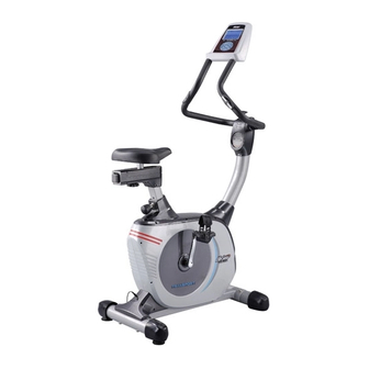
- Page 1 TRANSPORT PRO MAGNETIC UPRIGHT BIKE ITEM NO.: 20690 OWNER’S MANUAL IMPORTANT: Read all instructions carefully before using this product. Retain this owner’s manual for future reference. The specifications of this product may vary from this photo, subject to change without notice.
-
Page 2: Table Of Contents
TABLE OF CONTENTS WARRANTY ------------------------------------------------------------------------------- 2 IMPORTANT SAFETY INSTRUCTIONS ------------------------------------------- 3 PARTS LIST ------------------------------------------------------------------------------- 4 HARDWARE PACKING LIST --------------------------------------------------------- 6 TOOLS -------------------------------------------------------------------------------------- 6 OVERVIEW DRAWING ----------------------------------------------------------------- 7 ASSEMBLY INSTRUCTIONS --------------------------------------------------------- 8 OPERATING THE COMPUTER ------------------------------------------------------ 13 ADJUSTMENTS -------------------------------------------------------------------------- 204 MAINTENANCE -------------------------------------------------------------------------- 21 TROUBLESHOOTING ------------------------------------------------------------------ 21 WARM UP AND COOL DOWN ROUTINE ----------------------------------------- 22... -
Page 3: Warranty
ONE YEAR LIMITED WARRANTY LifeGear Inc. warrants to the original purchaser that this product is free from defects in material and workmanship when used for the purpose intended, under the conditions that it has been installed and operated in accordance with LifeGear's Owner's Manual. LifeGear's obligation under this warranty is limited to replacing or repairing free of charge, any parts which may prove to be defective under normal home use. -
Page 4: Important Safety Instructions
IMPORTANT SAFETY INSTRUCTIONS Basic precautions should always be followed, including the following important safety instructions when using this equipment. Read all instructions before using this equipment. Read all instructions and follow it carefully before using this equipment. Make sure the equipment is properly assembled and tightened before use. -
Page 5: Parts List
PARTS LIST Description Qty No. Description 001 Computer (XLG-903SPGM) 1 026 Washer Ø16xØ8x1.5t Computer Extension Wire I 1 027 Screw ST2.9x16 (500mm) Computer Extension Wire II 1 028 Seat Sliding Tube Bolt (700mm) 004 Handlebar Ø28x1.5t 1 029 Big Washer Ø8xØ20x2.0t Handlebar Foam Grip 2 030 Seat Adjustment Knob M8 Ø27xØ33x730... - Page 6 PARTS LIST Description Qty No. Description 051 Nut M10x1.25x10 2 063 Bearing 6003ZZ 052R Right Crank 1 064 Sensor with Wire L=750mm 052L Left Crank 1 065 Belt Pulley 260J6 053 Cover Cap Ø40xØ25x10 2 066 Belt PJ 410 J6 054R Right Shroud 1 067 Belt Pulley Shaft 054L Left Shroud...
-
Page 7: Hardware Packing List
HARDWARE PACKING LIST (7) Screw ST4.2x20mm (27) Screw ST2.9x16 (44) Carriage Bolt M8x90mm 5 PCS 13 PCS 2 PCS (45) Big Curve Washer (46) Cap Nut M8 (72) Bolt M8x90mm Ø8xØ20x2.0t 2 PCS 2 PCS 4 PCS TOOLS Allen Wrench S6 Multi Hex Tool with Phillips Screwdriver 1 PC S10, S13, S14, S15... -
Page 8: Overview Drawing
OVERVIEW DRAWING... -
Page 9: Assembly Instructions
ASSEMBLY INSTRUCTIONS Tool: Multi Hex Tool with Phillips Screwdriver S10, S13, S14, S15 Allen Wrench S6 1. Front/Rear Stabilizers and Right/Left Foot Pedals Installation Position the Front Stabilizer (43) in front of Main Frame (48) and align bolt holes. Attach the Front Stabilizer (43) onto the front curve of the Main Frame (48) with two M8x90mm Carriage Bolts (44), two Ø8xØ20x2.0t Big Curve Washers (45), and two M8 Cap Nuts (46). - Page 10 Hardware: (44) Carriage Bolt (45) Big Curve Washer (46) Cap Nut M8 (72) Bolt M8x90mm M8x90mm Ø8xØ20x2.0t 2 PCS 2 PCS 2 PCS 4 PCS ․․․․․․․․․․․․․․․․․․․․․․․․․․․․․․․․․․․․․․․․ Tool: Multi Hex Tool with Phillips Screwdriver S10, S13, S14, S15 Multi Hex Tool S10, S13, S17, S19 2.
- Page 11 Hardware: (7) Screw ST4.2x20mm (27) Screw ST2.9x16 2 PCS 5 PCS ․․․․․․․․․․․․․․․․․․․․․․․․․․․․․․․․․․․․․․․․ Tool: Allen Wrench S6 3. Handlebar Post and Handlebar Post Cover Installation Remove six M8x15 Bolts (19) and six Ø8xØ16x1.5t Curve Washers (20) from the Main Frame (48). Remove bolts and curve washers with the S6 Allen Wrench provided. Slide the Handlebar Post Cover (21) up to the Handlebar Post (14).
- Page 12 Tool: Multi Hex Tool with Phillips Screwdriver S10, S13, S14, S15 4. Handlebar, Front/Rear Decorative Covers for Handlebar Post, and Computer Installation Place the Handlebar (4) through clamp on the top end of the Handlebar Post (14). Connect the Computer Extension Wire II (3) from the Handlebar Post (14) to the Computer Extension Wire III (15) from the Handlebar (4).
- Page 13 5. AC Adapter Installation Plug one end of the AC Adapter (18) into the power jack of the Power Supply Wire (17) on the back of the Left Shroud (54L). Before plugging in, make sure to check carefully the specifications on the Adapter. Plug the other end of the AC Adapter (18) into the electrical wall outlet.
-
Page 14: Operating The Computer
OPERATING THE COMPUTER BUTTON FUNCTIONS: START/STOP: Press the START/STOP button to start or stop training. MODE: By holding the MODE button for two seconds the user can reset all values to 0. Press the MODE button to change the function from PROGRAMS, TIME, DISTANCE, CAL, TARGET, 10 intervals, GENDER, HEIGHT, WEIGHT, and AGE. - Page 15 About Display: STOP: Indicates the program selected has stopped. User is free to change the programs and the value of functions applied. PROGRAM: Indicates the programs selected from PROGRAM 0 to PROGRAM 19. LEVEL: Indicates the level of loading selected from LEVEL 1 to LEVEL 16. GENDER: Indicates the gender (Male or Female) selected.
- Page 16 DIST/FAT% Display: Indicates only one functional value of DIST (DISTANCE) or FAT% displayed depending on the programs. WATT/CAL Display: Indicates only one functional value of WATT or CAL displayed depending on the programs. T.H.R./PULSE Display: Indicates only one functional value of T.H.R (TARGET HEART RATE) or PULSE displayed depending on the programs.
- Page 17 Operating Ranges Values Range (Count up) Count down Preset Increment (Decrement) PROGRAM 0 ~ 19 19 ~ 0 LEVEL 1 ~ 16 16 ~ 1 GENDER Male, Female Male, Female Male TIME 0:00 ~ 99:59 99:00 ~ 5:00 0:00 1:00 HEIGHT (cm) 110.0 ~ 200.0 200.0 ~ 110.0...
- Page 19 BMR: Basal Metabolism Ratio BMI: Body Mass Index FAT%: Shows the body fat ratio. Operation Instructions Exercising With a Specific Goal: TIME Control: Sets up a period of time to exercise. (Except in Program 19) DISTANCE Control: Sets up a certain distance to exercise. (Except in Program 19) CALORIES Control: Sets up a certain calories to exercise.
- Page 20 Program 17, press the MODE button to select TIME, DISTANCE, CALORIES, and AGE. Then press the UP or DOWN button to adjust the values. Users may exercise in a period of time, a certain distance, or a certain calories want to burn with 55% Max Heart Rate in Program15, 75% Max Heart Rate in Program 16, and 85% Max Heart Rate in Program 17.
-
Page 21: Adjustments
ADJUSTMENTS Adjusting the Adjustable Leveler Turn the adjustable leveler on the rear stabilizer as needed to level the upright bike. Adjustable Leveler Adjusting the Seat Forward or Back Turn the seat adjustment knob to loosen the seat sliding tube. Slide the seat sliding tube forward or back to desired position and turn seat adjustment knob to tighten. -
Page 22: Maintenance
MAINTENANCE Cleaning The upright bike can be cleaned with a soft clean damp cloth. Do not use abrasives or solvents on plastic parts. Please wipe your perspiration off the upright bike after each use. Be careful not to get excessive moisture on the computer display panel as this might cause an electrical hazard or electronics to fail. -
Page 23: Warm Up And Cool Down Routine
WARM UP AND COOL DOWN ROUTINE The WARM-UP is an important part of any workout. The purpose of warming up is to prepare your body for exercise and to minimize injuries. Warm up for two to five minutes before aerobic exercising. It should begin every session to prepare your body for more strenuous exercise by heating up and stretching your muscles, increasing your circulation and pulse rate, and delivering more oxygen to your muscles. - Page 24 QUADRICEPS STRETCH With one hand against a wall for balance, reach behind you and pull your right foot up. Bring your heel as close to your buttocks as possible. Hold for 15 counts and repeat with left foot. INNER THIGH STRETCH Sit with the soles of your feet together and your knees pointing outward.
Need help?
Do you have a question about the 20690 and is the answer not in the manual?
Questions and answers