Table of Contents
Advertisement
Quick Links
Advertisement
Table of Contents

Related Manuals for LifeGear 20145HP


Summary of Contents for LifeGear 20145HP
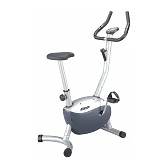
- Page 1 MAGNETIC UPRIGHT BIKE ITEM NO.: 20145HP OWNER’S MANUAL IMPORTANT: Read all instructions carefully before using this product. Retain this owner’s manual for future reference. The specifications of this product may vary from this photo, subject to change without notice. 2013, April...
-
Page 2: Table Of Contents
WARM UP AND COOL DOWN ROUTINE ----------------------------------------- 12 ONE YEAR LIMITED WARRANTY LifeGear Inc. warrants to the original purchaser that this product is free from defects in material and workmanship when used for the purpose intended, under the conditions that it has been installed and operated in accordance with LifeGear's Owner's Manual. -
Page 3: Safety Instructions
SAFETY INSTRUCTIONS Basic precautions should always be followed, including the following safety instructions when using this equipment: Read all instructions before using this equipment. Read all the instructions in this manual and do warm up exercises before using this equipment. Before exercise, in order to avoid injuring the muscle, warm-up exercise of every position of the body is necessary. -
Page 4: Adjustments
ADJUSTMENTS Adjusting the Tension Control Knob To increase the load, turn the tension control knob in a clockwise direction. To decrease the load, turn the tension control knob in a counterclockwise direction. Adjusting the Rear Stabilizer End Cap Turn the rear stabilizer end cap on the rear stabilizer as needed to level the bike. Adjusting the Seat Height Turn the round knob in a counterclockwise direction until the seat post can be slid up or down and then slide the seat post up or down direction to the suitable position. -
Page 5: Tools
DST (DISTANCE): Press the MODE button until the arrow points to DST; the monitor will display the accumulative distance traveled during workout. CAL (CALORIES): Press the MODE button until the arrow points to CAL; the monitor will display the total accumulated calories burned during workout. PUL (PULSE): Press MODE button until the arrow points to PUL and then hold both two hands on handlebar grip sensors, the screen will display your current heart rate figures and a heart symbol. -
Page 6: Parts List
PARTS LIST Description Qty No. Description 001 Main Frame 1 028 Tension Control Knob L=320 002 Front Stabilizer End Cap 2 029 Hex Nut M10 003 Rear Stabilizer End Cap 2 030 Pressing Belt Wheel 004 Front Stabilizer Ø50x1.5 1 031 Bearing 6000-2Z 005 Left Foot Pedal YH-4X 1 032 Washer Ø10.2xØ14x1.0 006 Right Foot Pedal YH-4X... -
Page 7: Overview Drawing
OVERVIEW DRAWING... -
Page 8: Assembly Instructions
ASSEMBLY INSTRUCTIONS Tool: Allen Wrench (S6) Multi Hex Tool with Phillips Screwdriver S13, S14, S15 1. Install the Front/Rear Stabilizers and Foot Pedals Remove four M8x15 Bolts (41) and four Ø20xØ8 Big Curve Washers (46) from the Front Stabilizer (4). Position the Front Stabilizer (4) in front of Main Frame (1) and align bolt holes. - Page 9 Tool: Multi Hex Tool with Phillips Screwdriver S13, S14, S15 2. Install the Seat Cushion and Seat Post Remove three M8 Locknuts (45) and three Ø8 Washers (48) from underside of the Seat Cushion (20). Guide bolts on underside of the Seat Cushion (20) through holes on top of the Seat Post (21), attach with three removed M8 Locknuts (45) and three Ø8 Washers (48).
- Page 10 Tool: 46 41 Allen Wrench (S6) 3. Handlebar Post Installation Remove four M8x15 Bolts (41) and four Ø20xØ8 Big Curve Washers (46) from the tube of the Main Frame (1). Connect the Sensor Wire (10) from the Main Frame (1) to the Middle Section Sensor Wire (13) from the Handlebar Post (27).
- Page 11 Tool: Allen Wrench (S6) 4. Install the Handlebar and Computer Remove two M8x15 Bolts (41) and two Ø8 Curve Washers (51) from the Handlebar Post (27). Insert the Hand Pulse Sensor Wires (52) into the hole on the Handlebar Post (27) and then pull them out from the top end of the Handlebar Post (27).
-
Page 12: Maintenance
MAINTENANCE Cleaning The upright bike can be cleaned with a soft cloth and mild detergent. Do not use abrasives or solvents on plastic parts. Please wipe your perspiration off the bike after each use. Be careful not get excessive moisture on the computer display panel as this might cause an electrical hazard or electronics to fail. -
Page 13: Warm Up And Cool Down Routine
WARM UP AND COOL DOWN ROUTINE A good exercise program consists of a warm-up, aerobic exercise, and a cool down. Do the entire program at least two to three times a week, resting for a day between workouts. After several months you can increase your workouts to four or five times per week. AEROBIC EXERCISE is any sustained activity that sends oxygen to your muscles via your heart and lungs. - Page 14 SIDE STRETCHES Open your arms to the side and lift them until they are over your head. Reach your right arm as far toward the ceiling as you can for one count. Repeat this action with your left arm. QUADRICEPS STRETCH With one hand against a wall for balance, reach behind you and pull your right foot up.
- Page 15 TOE TOUCHES Slowly bend forward from your waist, letting your back and shoulders relax as you stretch toward your toes. Reach as far as you can and hold for 15 counts. HAMSTRING STRETCHES Extend your right leg. Rest the sole of your left foot against your right inner thigh.
Need help?
Do you have a question about the 20145HP and is the answer not in the manual?
Questions and answers