Advertisement
Quick Links
Cautions, Warnings, and Regulatory Information
READ AND SAVE THESE INSTRUCTIONS Follow the instructions in this installation manual. These instructions must be followed to avoid damage to
this product and associated equipment. Product operation and reliability depend upon proper installation.
DO NOT INSTALL ANY SIMPLEX™ PRODUCT THAT APPEARS DAMAGED Upon unpacking your Simplex product, inspect the contents
of the carton for shipping damage. If damage is apparent, immediately file a claim with the carrier and notify an authorized Simplex
product supplier.
ELECTRICAL HAZARD Disconnect electrical field power when making any internal adjustments or repairs. All repairs should be
performed by a representative or an authorized agent of your local Simplex product supplier.
STATIC HAZARD Static electricity can damage components. Handle as follows:
• Ground yourself before opening or installing components.
• Prior to installation, keep components wrapped in anti-static material at all times.
EYE SAFETY HAZARD Under certain fibreoptic application conditions, the optical output of this device may exceed eye safety limits. Do
not use magnification (such as a microscope or other focusing equipment) when viewing the output of this device.
FCC RULES AND REGULATIONS – PART 15. This equipment has been tested and found to comply with the limits for a Class A digital device,
pursuant to Part 15 of the FCC Rules. These limits are designed to provide reasonable protection against harmful interference when the equipment
is operated in a commercial environment. This equipment generates, uses, and can radiate radio frequency energy and, if not installed and used in
accordance with the instruction manual, may cause harmful interference to radio communications. Operation of this equipment in a residential area is
likely to cause harmful interference in which case the user will be required to correct the interference at his own expense.
SYSTEM REACCEPTANCE TEST AFTER SOFTWARE CHANGES To ensure proper system operation, this product must be tested in accordance with
NFPA72® after any programming operation or change in site-specific software. Reacceptance testing is required after any change, addition or deletion
of system components, or after any modification, repair or adjustment to system hardware or wiring.
All components, circuits, system operations, or software functions known to be affected by a change must be 100% tested. In addition, to ensure that
other operations are not inadvertently affected, at least 10% of initiating devices that are not directly affected by the change, up to a maximum of 50
devices, must also be tested and proper system operation verified.
NFPA 72® is a registered trademark of the National Fire Protection Association.
Introduction to Amplifiers
Introduction
This publication describes the installation procedure for the 4100U and 4100ES Fire Alarm Control Units (FACU) family of digital and analog amplifiers.
Important: Verify FACU System Programmer, Executive, and Slave Software compatibility when installing, or replacing system components. Refer to
the Technical Support Information and Downloads website for compatibility information.
Overview
The digital and analog audio amplifiers provide analog audio power to the system speaker circuits. Digital amplifiers decode digitally encoded input
signals and analog amplifiers receive analog input signals. A speaker circuit consists of one or more speakers that are driven by the same physical
wiring. All of the 100 W amplifiers described in this document are single channel amplifiers; that is, each speaker circuit is driven by the same audio
signal. See the next section for a list of all 100 W amplifiers.
Digital/Analog Amplifiers Installation Instructions
579-174 Rev. Q
*0579174Q*
Advertisement

Related Manuals for Simplex 4100-1314


Summary of Contents for Simplex 4100-1314
- Page 1 DO NOT INSTALL ANY SIMPLEX™ PRODUCT THAT APPEARS DAMAGED Upon unpacking your Simplex product, inspect the contents of the carton for shipping damage. If damage is apparent, immediately file a claim with the carrier and notify an authorized Simplex product supplier.
- Page 2 Digital/Analog Amplifiers Installation Instructions 100 W Amplifiers Compatible with CSNAC Option Note: The following PIDs (example: 4100-1314) are compatible with all options (includes the CSNAC option)and 4100U Master Firmware Rev. 11.08 or later). Analog Amps: • 4100-1314 100 W Amp – 120 VAC, 25 VRMS •...
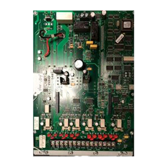
- Page 3 Digital/Analog Amplifiers Installation Instructions Figure 1 depicts the 100 W amplifier. NAC (SPEAKER CIRCUIT) TERMINAL BLOCK (TB1) EXPANSION NAC PORT 1 EXPANSION (P1) NAC PORT 2 (P3) NAC TROUBLE LEDS (LEDs 5 through 10) OUTPUT TROUBLE LED (LED2) DIGITAL AUDIO BAUD RATE/ DECODER ADDRESS DIP...
-
Page 4: Amplifier Specifications
Digital/Analog Amplifiers Installation Instructions Amplifier Specifications Digital and Analog Amplifiers The specifications below apply to both analog and digital amplifiers. Input voltage: 120 VAC, 60 Hz, 4A (US and Canadian Versions) Input: 220/230/240 VAC, 50 Hz/60 Hz, 2A DC supply capacity: 20.4-33 VDC, 0-9.57 A load, 2 V p-p ripple (max.) Table 1: Amplifier Battery Current Draw Amplifier Status Average Current Draw... - Page 5 Digital/Analog Amplifiers Installation Instructions Figure 3: Card Addresses page 5 579-174 Rev. Q...
- Page 6 Digital/Analog Amplifiers Installation Instructions Power Wiring (AC and Battery) Overview The amplifier is powered through the Power Distribution Module (PDM). The PDM takes power directly from a dedicated AC line and the two backup batteries, and distributes power to each bay in the cabinet. Power Distribution Module Connections The Power Distribution Module (PDM) connects to every power supply and 100 W amplifier in each back box.
- Page 7 Digital/Analog Amplifiers Installation Instructions Installing the Amplifier onto the PDI The amplifier assembly is designed to be mounted on the PDI in a FACU expansion bay. The module should be mounted onto the rightmost side of the PDI. Lower the amplifier into the bay by placing the two tabs on the back of the amplifier assembly into the two slots on the bottom of the bay. Then use the bottom left connector on the back side of the amplifier to connect to the PDI as shown in Figure 5, below.
- Page 8 Digital/Analog Amplifiers Installation Instructions Amplifier Field Wiring Overview This section contains amplifier field wiring guidelines and illustrations, including speaker circuit wiring distances. The information covers all types of wiring, with and without backup amplifiers, NAC expansion modules, Constant Supervision NAC (CSNAC) modules, and Class A adapters. Note: TrueAlert ES speaker appliances have a maximum wire length.
-
Page 9: Class B Wiring
Digital/Analog Amplifiers Installation Instructions Class B Wiring Note: This is the 733-894. Figure 6: Class B Wiring Note: For guidance regarding proper wiring practice when using the TrueAlert ES speaker appliances, refer to the Speaker Wiring Application Guidelines in the ES-PS IDNAC Card Installation Instructions, 579-1289. •... -
Page 10: Class A Wiring
Digital/Analog Amplifiers Installation Instructions • Backup audio wiring is unsupervised. • Maximum speaker circuit current is 2 A per circuit. • Total available power is 100 W (4 A @ 25 VRMS, 1.414 A @ 70.7 VRMS). • Terminal designations "+" and "-" are for the alarm state. •... - Page 11 Digital/Analog Amplifiers Installation Instructions • Total available power is 100 W (4 A @ 25 VRMS, 1.414 A @ 70.7 VRMS). • Terminal designations "+" and "-" are for the alarm state. • When required, shields are normally connected to 0 V as shown. Alternate shield termination using Earth ground is provided on the amplifier chassis.
- Page 12 100W 25V: 1.3uF 100W 70V: 0.15uF • Consult your local Simplex Office if installing a 70V CSNAC system with more than 6000ft of total wire to any single amplifier. Additional equipment may be needed. • For guidance regarding proper wiring practice when using TrueAlert ES speaker appliances, refer to the Speaker Wiring Application Guidelines in the ES-PS IDNAC Card Installation Instructions, 579-1289.
-
Page 13: Led Indications
Digital/Analog Amplifiers Installation Instructions LED Indications LEDs The amplifier LEDs are summarized in the table below. Table 4: LED Indications LED # LED Name Meaning Color LED1 COMMS TBL Steadily on when the amplifier is not communicating with the system CPU Yellow LED2 OUT_TBL... - Page 14 © 2019 Johnson Controls. All rights reserved. All specifications and other information shown were current as of document revision and are subject to change without notice. Additional listings may be applicable, contact your local Autocall product supplier for the latest status. Listings and approvals under Tyco Fire & Security GmbH, and the product names listed in this material are marks and/or registered marks. Unauthorized use is strictly prohibited. NFPA 72 and National Fire Alarm Code are registered trademarks of the National Fire Protection Association (NFPA).
Need help?
Do you have a question about the 4100-1314 and is the answer not in the manual?
Questions and answers