Advertisement
Quick Links
Cautions and
Warnings
In this
publication
Introduction
READ AND SAVE THESE INSTRUCTIONS
manual. These instructions must be followed to avoid damage to this product and
associated equipment. Product operation and reliability depend upon proper installation.
DO NOT INSTALL ANY SIMPLEX PRODUCT THAT APPEARS DAMAGED
unpacking your Simplex product, inspect the contents of the carton for shipping damage.
If damage is apparent, immediately file a claim with the carrier and notify an authorised
Simplex product supplier.
ELECTRICAL HAZARD
adjustments or repairs. All repairs should be performed by a representative or authorised
agent of your local Simplex product supplier.
- Static electricity can damage components. Handle as follows:
STATIC HAZARD
• Ground yourself before opening or installing components
• Prior to installation, keep components wrapped in anti-static material at all times
SYSTEM REACCEPTANCE TEST AFTER SOFTWARE CHANGES
system operation, this product must be tested in accordance with AS1670.1, after any
programming operation or change in site-specific software. Reacceptance testing is
required after any change, addition or deletion of system components, or after any
modification, repair or adjustment to system hardware or wiring. All components, circuits,
system operations, or software functions known to be affected by a change must be 100%
tested. In addition, to ensure that other operations are not inadvertently affected, at least
10% of initiating devices that are not directly affected by the change, up to a maximum of
50 devices, must also be tested and proper system operation verified.
This publication discusses the following topics:
Introduction to the MX Digital Loop Card
Installing the MX Digital Loop Card
Configuring the MX Digital Loop Card
Wiring the MX Digital Loop Card to Addressable Devices
Compatible MX Addressable Devices
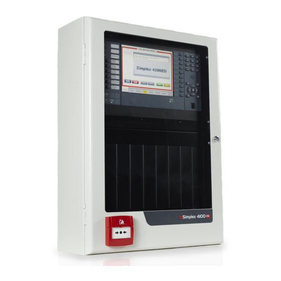
The 4100-6077AU MX Digital Loop Card is a 4 x 10 inch (double-height) PDI module
that interfaces a single MX Digital Loop to the 4100ESi fire panel.
Features:
•
4 x 10 inch double-height PDI module
•
Interfaces MX Loop to 4100ESi
•
Supports up to 250 MX devices
•
500mA Loop power
Electrically isolated MX Loop with earth fault monitoring
•
- Follow the instructions in this installation
- Disconnect electrical field power when making any internal
Topic
1
4100-6077AU
MX Digital Loop Card
Installation Instructions
- Upon
- To ensure proper
Page
2
4
6
8
10
LT0638 Iss 1.1 7/2017
Advertisement

Related Manuals for Simplex 4100ESi


Summary of Contents for Simplex 4100ESi
- Page 1 - Upon DO NOT INSTALL ANY SIMPLEX PRODUCT THAT APPEARS DAMAGED unpacking your Simplex product, inspect the contents of the carton for shipping damage. If damage is apparent, immediately file a claim with the carrier and notify an authorised Simplex product supplier.
-
Page 2: Physical Specifications
Introduction to the MX Digital Loop Card The MX Digital Loop Card provides MX loop communications for the Simplex 4100ESi Overview fire alarm panel via a single electrically isolated MX Digital loop. It supports up to 250 MX devices - detectors and modules - and provides up to 500mA of loop power. - Page 3 COMM Loss On when the card is not On steady during communicating with the communications loss. Yellow 4100ESi Central Processing Flashing in local mode Unit (CPU) Earth Fault Earth fault trouble On steady when earth fault is detected on the MX loop...
- Page 4 Step 1: Installing the MX Digital Loop Card The MX Digital Loop Card mounts in a Cardcage/PDI bay of a 4100ESi panel. It can be Installation of mounted on any available block - see Figure 2. Secure with the screws supplied in the MX the 4100-6077 Digital Loop Card kit.
- Page 5 Cabinet The ME0516 bracket is not suitable for mounting 4100-6077AU cards in the standard Simplex expansion bay. The earlier 4100-6077LIM version of the loop card should not be mounted on the ME0516 Legacy/Dual Bracket (ME0516), as the resulting module width is too wide and may interfere with other modules and equipment.
- Page 6 (SW100-1) must be set to ON Position 8 is LSB (least significant bit) OFF = ACTIVE Figure 4. DIP Switch SW100 The MX Digital Loop Card is programed using the 4100ESi Programmer. Refer to Programming LT0619 4100ESi Programming Manual for details. LT0638 Iss 1.1 7/2017...
- Page 7 Step 2: Configuring the MX Digital Loop Card Table 2. Module DIP Addresses SW100-2 SW100-3 SW100-5 SW100-7 SW100-2 SW100-3 SW100-5 SW100-7 SW100-4 SW100-6 SW100-4 SW100-6 SW100-8 SW100-8 LT0638 Iss 1.1 7/2017...
- Page 8 Step 3: Wiring the MX Digital Loop Card to Addressable Devices The field wiring of the MX Digital Loop Card shall follow the specifications below: Field Wiring • Maximum devices per loop: 250 Specifications • MX device addresses allowed: 1 to 250 •...
- Page 9 These are not shown in Figure 5. These are not required with the 4100-6077AU as it includes short circuit protection. Full details of the MX Device and Loop wiring can be found in LT0432 4100ESi Field Wiring Diagrams.
-
Page 10: Appendix A: Mx Addressable Devices
Johnson Controls • Southbank, VIC • 3006 • AUS LT0638 Iss 1.1 7/2017 www.simplex-fire.com © 2017 Johnson Controls. All rights reserved. All specifications and other information shown were current as of document revision date and are subject to change without notice.
Need help?
Do you have a question about the 4100ESi and is the answer not in the manual?
Questions and answers