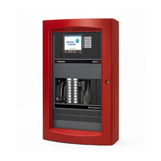
Simplex 4100 Operation
Front panel
Hide thumbs
Also See for 4100:
- Operator's manual (100 pages) ,
- Service instructions manual (98 pages) ,
- Installation manual (97 pages)

Subscribe to Our Youtube Channel
Related Manuals for Simplex 4100


Summary of Contents for Simplex 4100
- Page 1 4100 Fire Alarm Front Panel Operation Version 9.X Addendum 579-126 Rev. B firealarmresources.com...
- Page 2 Changes The following changes have been made to this document for Revision B. Rev. Page Change 1-11 Add Display First Alarm alarm list feature description. Describe how to identify Version Mismatch Condition. CHANGE PAGE THIS PAGE IS BLANK. firealarmresources.com...
- Page 3 Copyrights and Trademarks Copyright Simplex Time Recorder Co., 2000. All rights reserved. Printed in the United Copyrights States of America. Copyright 2000 Simplex International Time Equipment Co., Ltd., Mississauga, Ontario L4V 1H3 Canada. All specifications and other information shown were current as of publication, and are subject to change without notice.
- Page 4 This page is blank firealarmresources.com...
- Page 5 DO NOT INSTALL ANY SIMPLEX PRODUCT THAT APPEARS DAMAGED. Upon unpacking your Simplex product, inspect the contents of the carton for shipping damage. If damage is apparent, immediately file a claim with the carrier and notify Simplex.
- Page 6 BLANK PAGE firealarmresources.com...
-
Page 7: Table Of Contents
Related Documents ..................xii Chapter 1. Version 9.X Overview Introduction....................1-1 In this Chapter................... 1-1 Version 9.X System Description..............1-2 4100/4020 Version 9.X Compatibility............1-2 TrueAlert Addressable Controller............. 1-2 Virtual NACs .................... 1-3 TrueAlert Appliances................1-4 VNAC Status .................... 1-4 TrueAlert Controller ................. - Page 8 Activate all Appliance LEDs on all TrueAlert Controller Channels ..3-2 Single Appliance Test Mode (Manual Real Appliance Test)....3-2 Global Silent Appliance Test ..............3-3 Manual Silent Appliance Test..............3-3 4100/4020 WalkTest................. 3-3 Appliance LED Activation................3-4 Procedure ....................3-4 Manual Real Appliance Test................. 3-5 Procedure ....................
- Page 9 Figures Figure 1-1. Graphical Representation of Virtual NACs ........1-3 Figure 1-2. Device Address Field ..............1-9 firealarmresources.com...
- Page 10 BLANK PAGE firealarmresources.com...
-
Page 11: How To Use This Publication
How to Use this Publication Conventions Used Before you start using the 4100 Fire Alarm Front Panel Operation Version 9.X Addendum, it's important to understand the conventions used in this publication. The following conventions are used in this publication to identify special names or text. -
Page 12: About This Document
About this Document Introduction This publication has been created as an addendum to the 4100/4100+ Fire Alarm Operating Instructions (574-018), to document the operation of the TrueAlert features specific to Version 9.X of the 4100/4020 firmware. Applications may vary due to custom programming and local code requirements. -
Page 13: Chapter 1. Version 9.X Overview
Version 9.X Overview Introduction This chapter gives an overview of Version 9.X functionality and describes the operational characteristics and the operator interface of the 4100/4020 Fire Alarm Control Panel (FACP) with Version 9.X firmware installed. In this Chapter This chapter discusses the topics listed in the following table. Refer to the page number listed after the topic for information on that topic. -
Page 14: Version 9.X System Description
4100/4020 Version 9.X Compatibility To use TrueAlert functionality, Version 9.X (or higher) of the 4100/4020 firmware is required. In addition, the 4100/4020 requires the use of a TrueAlert Addressable Controller connected to the 4100/4020 (via an RUI card) as an external slave. -
Page 15: Virtual Nacs
Virtual NACs A Virtual NAC (or VNAC) is a collection of TrueAlert appliances grouped together to allow control functions. Each 4100/4020 system can support up to 64 Virtual NACs (8 default VNACs plus 56 user-defined VNACs). A VNAC can be made up of TrueAlert appliances from any or all of the TrueAlert Controller channels. -
Page 16: Truealert Appliances
Version 9.X System Description, Continued TrueAlert Appliances TrueAlert Appliances can have one of the following status conditions: • Normal • Missing (trouble) • Wrong appliance (trouble) • Short (trouble – isolator only) VNAC Status VNACs have the following status information: •... -
Page 17: Effects On The Operator Interface
Effects on the Operator The Version 9.X TrueAlert modifications have the following effects on the Interface 4100/4020 Operator Interface: • TrueAlert appliances are visible as points with custom labels. However, appliances cannot be individually controlled and there is no “ON/OFF” status. -
Page 18: Operational Characteristics
The TrueAlert controller gathers a roster of appliances on each of its TrueAlert channels. This roster is then compared to the appliance download information sent by the 4100/4020 Master. If any extra appliances are found, the “Extra Appliance Trouble” status (one status report per TrueAlert Controller) is sent to the 4100/4020. -
Page 19: Appliance Control With Vnacs
• Computer Port commands (SET, TRACK) The same rules applied to standard 4100/4020 Signal Circuits apply to the VNACs. A point is only turned on if the requested priority is ‘higher’ than the point’s current priority and if the point is not in manual override trouble. If the point is in manual override trouble, any command other than another manual operation is ignored until the point is restored to automatic operation. -
Page 20: Computer Port/Sdact
Computer Port/SDACT Both TrueAlert appliances and the Virtual NACs will report their statuses on the 4100/4020’s Computer Port. In addition, the SHOW command is expanded to display the Virtual NAC and appliance ‘function screen’ data. The information in the Unsolicited Output section also applies to the 4100/4020 SDACT. -
Page 21: Operator Interface
Operator Interface TrueAlert Appliances Individual TrueAlert appliances are called-up on the 4100/4020 Operator Interface Panel via the ‘address’ key. The card number, channel number, and appliance number must be known in order to select the point for viewing from the Operator Interface Panel. -
Page 22: Virtual Nacs
Operator Interface, Continued Function Key Display Press NEXT again. The appliance’s coding operation screen is displayed: (Continued) 40 CHARACTER CUSTOM LABEL CODING OPERATION: TEMPORAL Note: If an A/V appliance is being reported, “TEMPORAL” refers to the audible appliance’s coding operation. If you press NEXT again, the TrueAlert diagnostic features display one feature at a time. -
Page 23: Display First Alarm
Operator Interface, Continued Display First Alarm The Display First Alarm alarm list feature (which enables the automatic display of the first alarm) is configurable via the Programmer (disabled by default). If this option has been programmed for your panel, the Operator Interface Panel shows the first (oldest) alarm whenever a single or multiple alarm conditions is reported. - Page 24 Operator Interface, Continued Display First Alarm Multiple Event Unacked Alarm Points (Continued) EAST WING, THIRD FLOOR, HEAT Show first unacked alarm Heat Detector FIRE ALARM event point information and (Second line alternates once a second) EAST WING, THIRD FLOOR, HEAT alternate second line with Press <Alarm Ack>...
-
Page 25: Introduction
System Operations Introduction This chapter shows how to handle abnormal system operations for a typical 4100/4020 FACP running Version 9.X firmware. Your system operation may vary due to custom programming and local code requirements. In this Chapter This chapter discusses the topics listed in the following table. Refer to the page number listed after the topic for information on that topic. -
Page 26: Handling Abnormal Conditions
The TrueAlert appliance in trouble is located on the TrueAlert Addressable Appliance Controller which is regarded by the 4100/4020 as a ‘slave’ card. The 4100 Programming Unit Programmer Report lists the card address for the TrueAlert Addressable Controller as Card Address 4 on this system. The Appliance Custom Label thoughtfully provided the Channel and Appliance Number, so we have the appliance address: 4-1-4. -
Page 27: How To Identify A Version Mismatch Condition
System Trouble Log in the usual manner. Runtime Viewing of Node Pair Version Numbers From a 4100 node’s network node identification screen, you have the ability to see the communication version number between the node and all other nodes on the network. - Page 28 Mismatch Condition gather the information, the display shows an asterisk (*). (Continued) NODE 4 VER#* *Node 4: 4100 SYSTEM (ENHANCED) The Version Checking example shows that at least two of the Network Nodes are mismatched and require a build. firealarmresources.com...
-
Page 29: Handling Disabled Conditions
Handling Disabled Conditions Introduction As the operator of a 4100/4020 FACP, you must use the Operator Interface keypad to disable a zone, outputs to fault warning routing equipment, controls for automatic fire protection equipment, outputs to fire alarm appliances, or outputs to fire alarm routing equipment. -
Page 30: How To Enable A Vnac
Handling Disabled Conditions, Continued How to Enable a VNAC Note: To perform this procedure, you must be at the correct Access Level or higher. Use the following procedure to enable a VNAC: Press <TBL ACK> until the VNAC signal number is displayed. VIRTUAL NAC 10 –... -
Page 31: Chapter 3. Truealert Diagnostics
Chapter 3 TrueAlert Diagnostics Introduction There are many diagnostic capabilities available with a TrueAlert Addressable Controller SLC channel that are not available on a traditional NAC. This chapter describes the diagnostic operations that can be used with the TrueAlert Addressable Controller. In this Chapter This chapter discusses the topics listed in the following table. -
Page 32: About Truealert Diagnostics
To aid in finding the appliance, the 4100/4020 has the capability of turning on all of the LEDs on a TrueAlert Addressable Controller via the Operator Interface Panel. This allows the technician to go out into the building and look for the appliance without a lit LED. -
Page 33: Global Silent Appliance Test
The 4100/4020 system with a TrueAlert Addressable Controller supports Non-Voice WalkTest in the same manner as a 4100/4020 system without a controller. VNACs can be put into WalkTest groups, and the appliances will sound out the address of the activated peripheral although the TrueAlert strobes will not flash. -
Page 34: Appliance Led Activation
Use the following procedure to activate all of the TrueAlert Appliance LEDs assigned to a particular TrueAlert Addressable Controller. Log on the 4100/4020 at the appropriate Access Level. On the Operator Interface Panel, go to the TrueAlert appliance function screen and turn on the appliance LEDs on the TrueAlert Addressable Controller. -
Page 35: Manual Real Appliance Test
Manual Real Appliance Test Procedure Note: In order for Diagnostics to operate properly all appliances must be inactive prior to diagnostic activation. Use the following procedure to place the system in the Single Appliance Test Mode to run the Manual Real Appliance Test. Go to the Operator Interface Panel and enter the address of a TrueAlert appliance assigned to a particular TrueAlert Addressable Controller. -
Page 36: Global Silent Appliance Test Mode
Wait a minimum of one to two minutes before testing appliances to ensure that the diagnostics are active. Initiate an alarm on the 4100/4020 and verify that the LED on each A/V appliance turns on steady without audibles or strobes. -
Page 37: Manual Silent Appliance Test Mode
Use the following procedure to initiate the test. At the 4100/4020 Operator Interface Panel, enter the address of a TrueAlert appliance assigned to a particular TrueAlert Addressable Controller. Go to the TrueAlert Appliance Function Screen and enable Device Test Mode and Silent Test Mode at the same time. -
Page 38: Truealert Appliance Walktest
The TrueAlert Addressable Controller will fully support the Non-Voice Simplex WalkTest. Use the following procedure to initiate the TrueAlert WalkTest. Put the 4100/4020 Operator Interface Panel into WalkTest and verify the WalkTest trouble reports. Initiate a monitor point from each WalkTest group and verify that the correct code is generated on the appropriate appliance. - Page 39 BLANK firealarmresources.com...
- Page 40 PAGE BLANK SEC-31-503 Rev. B 579-126 Simplex Time Recorder Company Westminster, Massachusetts 01441-0001 U.S.A. (574-637) Simplex Time Recorder Co. Simplex Plaza Gardner, Massachusetts 01441-0001 U.S.A. Ed 11 96 firealarmresources.com...
Need help?
Do you have a question about the 4100 and is the answer not in the manual?
Questions and answers