Table of Contents
Advertisement
Quick Links
ORIGINAL INSTRUCTIONS
S/N: 1175 AND ABOVE
PLEASE CONTACT GAGE BILT FOR
ALL OTHER SERIAL NUMBERS.
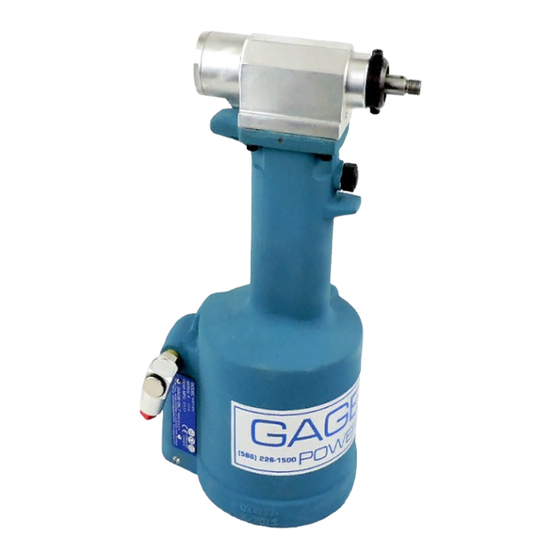
GB740
INSTALLATION TOOL
GAGE BILT TOOLS ARE AVAILABLE WORLDWIDE
E-MAIL US FOR A DISTRIBUTOR NEAR YOU.
GAGE BILT
44766 Centre Court Clinton Twp. MI 48038 USA
Ph: +1 (586) 226-1500 Fax: +1 (586) 226-1505
solutions@gagebilt.com / www.gagebilt.com
MADE in USA
Advertisement
Table of Contents

Related Manuals for Gage Bilt GB740


Summary of Contents for Gage Bilt GB740
- Page 1 PLEASE CONTACT GAGE BILT FOR ALL OTHER SERIAL NUMBERS. GB740 INSTALLATION TOOL GAGE BILT TOOLS ARE AVAILABLE WORLDWIDE E-MAIL US FOR A DISTRIBUTOR NEAR YOU. GAGE BILT 44766 Centre Court Clinton Twp. MI 48038 USA Ph: +1 (586) 226-1500 Fax: +1 (586) 226-1505 solutions@gagebilt.com / www.gagebilt.com...
-
Page 2: Table Of Contents
Overhaul ....................................13 Parts Lists.................................... 14-16 DEXRON® III Oil Safety Data (SDS) ............................17 Nose Assembly Selection Chart / Accessories ........................18 Accessories ....................................20 GB740 S/N 1175 AND ABOVE Rev. 5/22 PLEASE CONTACT GAGE BILT FOR ALL OTHER SERIAL NUMBERS. -
Page 3: Eu Conformity And Warranty
GAGE BILT DECLARATION OF CONFORMITY MANUFACTURER: Gage Bilt Inc. 44766 Centre Ct. Clinton Twp. Michigan U.S.A. +1(586-226-1500) WE DECLARE THAT THE EQUIPMENT SPECIFIED HEREIN CONFORMS TO THE FOLLOWING DIRECTIVES AND STANDARDS Machinery Directive 2006/42/EC EN12100-1 & EN12100-2 EN792-1:2000+A1 EU REPRESENTATIVE Edgar Hausmann GmbH Förster-Busch-Str. -
Page 4: Description And Technical Specifications
90 psi (6.2 bar) of air pressure at the air inlet. The GB740 installation tool operates on 90 to 100 psi. (6.2-6.9 bar) of air pressure, with 90 psi. (6.2 bar) providing the maximum efficiency. At 90 psi. (6.2 bar), the GB740 does not exceed 81.5 dB(A) and consumes .30 SCF/cycle (8.50 L/cycle). -
Page 5: Description Of Functions
DESCRIPTION OF FUNCTIONS Hanger Head Cylinder Assembly Actuator Assembly-Air Actuator Lever Assembly Handle Assembly Air Inlet Image may not reflect actual tool GB740 S/N 1175 AND ABOVE Rev. 5/22 PLEASE CONTACT GAGE BILT FOR ALL OTHER SERIAL NUMBERS. -
Page 6: Warnings
4. Support the weight of the tool in a stand, tensioner or balancer, because a lighter grip can then be used to support the tool. GB740 S/N 1175 AND ABOVE Rev. 5/22 PLEASE CONTACT GAGE BILT FOR ALL OTHER SERIAL NUMBERS. -
Page 7: Principle Of Operation
Air Piston moves down Air exhaust Air exhaust Pressurized Oil Pressurized Air Unpressurized Oil Unpressurized Air Image may not reflect actual tool GB740 S/N 1175 AND ABOVE Rev. 5/22 PLEASE CONTACT GAGE BILT FOR ALL OTHER SERIAL NUMBERS. -
Page 8: How To Set-Up The Gb740
NOSE ASSEMBLY HEAD CYLINDER FASTENER WORK RED SHIPPING PLUG ACTUATOR AIR INLET USER QUICK DISCONNECT FITTING AIR HOSE Image may not reflect actual tool GB740 S/N 1175 AND ABOVE Rev. 5/22 PLEASE CONTACT GAGE BILT FOR ALL OTHER SERIAL NUMBERS. -
Page 9: How To Use The Gb740
Exert firm pressure against fastener during installation. Press actuator to start cycle. Release actuator as soon as fastener breaks. Repeat steps 1-4. Images may not reflect actual tool or fastener GB740 S/N 1175 AND ABOVE Rev. 5/22 PLEASE CONTACT GAGE BILT FOR ALL OTHER SERIAL NUMBERS. -
Page 10: Maintenance
WARNING: Tool must be maintained in a safe working condition at all times and examined on a daily basis for damage or wear. Any repair must be done by qualified personnel trained on Gage Bilt procedures. WARNING: Excessive contact with hydraulic oil and lubricants must be avoided. -
Page 11: Filling And Bleeding
Add dimension (A) to dimension (B). If stroke doesn’t check 1.330" (33.8 mm) min. (See figures below) follow bleeding procedure above until stroke met. For your consideration, Gage Bilt offers a depth gage (Pt.# A-1935) to help simplify and more accurately check your tool stroke. Please contact Gage Bilt for more information. -
Page 12: Troubleshooting
Replace worn or broken parts. Clean the surface the jaws ride on. Stems lodged side by side in the follower. Disassemble, remove stems, and reassemble. Incorrect follower. GB740 S/N 1175 AND ABOVE Rev. 5/22 PLEASE CONTACT GAGE BILT FOR ALL OTHER SERIAL NUMBERS. -
Page 13: Overhaul
Perform overhaul in a clean, well lit area using care not to scratch or nick any smooth surface that comes in contact with an o'ring. Use of Lubriplate® (Gage Bilt part no. 402723) or other lubricant is recommended during reassembly to prevent tearing or distorting of o'rings. - Page 14 Insert and turn 5/8” open end box wrench / adjustable wrench and snug tight approximately 1/4-1/2 turn. Re-attach the actuator lever assembly (704343) including pin-slotted (400608) to the handle assembly (744129). GB740 S/N 1175 AND ABOVE Rev. 5/22 PLEASE CONTACT GAGE BILT FOR ALL OTHER SERIAL NUMBERS.
- Page 15 Valve spring installation tool (744251) will facilitate the proper installation of the spring (744144). Valve sleeve (743144) can be pulled out using valve sleeve removal tool (744152). GB740 S/N 1175 AND ABOVE Rev. 5/22 PLEASE CONTACT GAGE BILT FOR ALL OTHER SERIAL NUMBERS.
-
Page 16: Parts Lists
PARTS LIST GB740 S/N 1175 AND ABOVE Rev. 5/22 PLEASE CONTACT GAGE BILT FOR ALL OTHER SERIAL NUMBERS. -
Page 17: Dexron® Iii Oil Safety Data (Sds)
Use material for its intended purpose or recycle if possible. Oil collection services are available for used oil recycling or disposal. Place contaminated materials in containers and dispose of in a manner consistent with applicable regulations. GB740 S/N 1175 AND ABOVE Rev. 5/22 PLEASE CONTACT GAGE BILT FOR ALL OTHER SERIAL NUMBERS. -
Page 18: Nose Assembly Selection Chart / Accessories
GB740 ACCESSORIES Approved for use on Gage Bilt CE installation tools and/or other manufacturer’s CE approved tools of similar design. (Sold Separately) NOSE ASSEMBLY SELECTION CHART OFFSET STRAIGHT RIGHT ANGLE (Sold Separately) (Sold Separately) (Sold Separately) FASTENER DIA. STRAIGHT RIGHT ANGLE... - Page 19 This page intentionally left blank. GB740 S/N 1175 AND ABOVE Rev. 5/22 PLEASE CONTACT GAGE BILT FOR ALL OTHER SERIAL NUMBERS.
-
Page 20: Accessories
Gage Bilt offers a wide selection of standard and custom kits tailored to your needs. Contact us for more information. Approved Accessories Cont. Approved for use on Gage Bilt CE installation tools and/or other manufacturer’s CE approved tools of similar design. (Sold Separately) Catcher Bag-Stem Air Bleeder Assembly...
Need help?
Do you have a question about the GB740 and is the answer not in the manual?
Questions and answers