Advertisement
Quick Links
Advertisement

Related Manuals for Gage Bilt GB734SHV


Summary of Contents for Gage Bilt GB734SHV
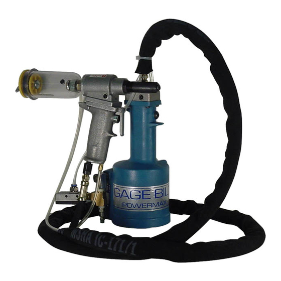
- Page 1 GB734SHV INSTALLATION TOOL GAGE BILT TOOLS ARE AVAILABLE WORLDWIDE E-MAIL US FOR A DISTRIBUTOR NEAR YOU. GAGE BILT Inc. GAGE BILT 44766 Centre Court (586) 226-1500 Clinton Twp. MI 48038 (586) 226-1505 Fax MADE IN U.S.A. e-mail:solutions@gagebilt.com / www.gagebilt.com...
-
Page 2: Table Of Contents
TABLE OF CONTENTS Description Page Warnings ..........................3 Description, Maintenance ..........4 and Hydraulic Thread Preparation Filling & Bleeding ........................5 Troubleshooting ........................6 Overhaul, Disassembly and Parts List ................7-10 ..................... 11 DEXRON® III Oil Safety Data Nose Assembly Selection Chart ................... 12 EU Conformity and Warranty .................... -
Page 3: Warnings
73.2 dB (A). In this daily basis for damage or wear. Any repair should condition the max level was 81.5 dB (A). Therefore, be done by qualified personnel trained on Gage Bilt it is required where prolonged use, hearing procedures. -
Page 4: Description, Maintenance And Hydraulic Thread Preparation
The GB734SHV split handle riveter operates on a wide range of air pressure, with 90 to 100 psi. (6-2-6.9 bar)providing maxi- mum efficiency. At 90 psi. (6.2 bar), the GB734SHV does not exceed 81.5 dB (A) and consumes 3 cfm at 20 cycles per minute. -
Page 5: Filling & Bleeding
FILLING & BLEEDING PROCEDURE: NOTE: Air Bleeder Assy (704153) and Fill Bottle (745263) are required. NOTE: To replace a small amount of oil follow BLEEDING steps 5-6. WARNING: Do not cycle tool without air bleeder assy (704153), or the screw and stat-o-seal, installed in tool head. Severe personal injury could result. CAUTION: Before filling handle assy (744129), air piston assy (744121) should be all the way down. -
Page 6: Troubleshooting
TROUBLESHOOTING Providing all maintenance conditions have been met, follow this systematic approach to diagnosis. 1. MORE THAN ONE PULL IS REQUIRED TO BREAK RIVET. a) Tool needs to be bled. (See filling and bleeding instructions.) b) Spring has fatigued, replace. c) Jaws are stripped or packed with chips. -
Page 7: Overhaul, Disassembly And Parts List
WARNING: Tool must be maintained in a safe working condition at all times and examined on a regular daily basis for damage or wear. Any repair should be done by qualified personnel trained on Gage Bilt procedures. WARNING: When operating, repairing or overhauling tool, wear approved eye protection. Do not look in front of tool or rear of tool when installing fastener. - Page 8 HEAD WARNING: Dispose of Hydraulic Oil in accordance with applicable regulations. Remove nose assy from tool before attempting disassembly of head cylinder assy. Remove end cap (734111-1). Push against threaded end of piston (734107) to slide it out of head cylinder assy (734104). Be careful not to damage threads or cause burrs on polished piston (734107) surface.
- Page 9 HANDLE To inspect air cylinder bore, remove base cover (744124). Any further disassembly will require removal of the manifold-handle (744303) first. For complete disassembly, start by removing base cover (744124). Next, holding tool upright, remove four button-head cap screws (A-928). Lift manifold-handle (744303) from handle assy (744129) and set aside o'ring (S832) and gasket (704129). Empty all hydraulic oil into an approved container and dispose of in accordance with all environmental regulations applicable in your area.
- Page 10 A-506 - TEE A-216 - FITTING 703582 - TUBING (2FT.) A-503 (TO A-216 (2) ADAPTER A-216 (TO HANDLE) 703518 - MUFFLER 703506 - BOTTLE, BUSHING AND CAP ASSEMBLY A-508 - ADAPTER 703515 - VACUUM REGULATOR 700440 - FITTING 703537 - FITTING ASSEMBLY 703589- TUBING (TO 703537 &...
-
Page 11: Dexron® Iii Oil Safety Data
DEXRON® III OIL SAFETY DATA FIRST AID MEASURES Eye: No specific first aid measures are required. As a precaution, remove contact lenses, if worn, and flush eyes with water. Skin: No specific first aid measures are required. As a precaution, remove clothing and shoes if contaminated. To remove the material from skin, use soap and water. -
Page 12: Nose Assembly Selection Chart
XX-703-18V SEE CHART 20518 405371 10757 70820 SEE CHART SPRING ANVIL HOLDER COLLET CHART XX-734A-20V SEE CHART 10935 28819 400777 405371 70820 ANVIL HOLDER COLLET CHART O'RING CHART SPRING XX-743-24V SEE CHART 10951 20867 400777 50626 70820 ANVIL HOLDER COLLET CHART O'RING CHART... -
Page 13: Eu Conformity And Warranty
GAGE BILT DECLARATION OF CONFORMITY MANUFACTURER: Gage Bilt Inc. 44766 Centre Ct. Clinton Twp. Michigan (586-226-1500) WE DECLARE THAT THE EQUIPMENT SPECIFIED HEREIN CONFORMS TO THE FOLLOWING DIRECTIVES AND STANDARDS Machinery Directive 2006/42/EC EN12100-1 & EN12100-2 EN792-1:2000+A1 EU REPRESENTATIVE Edgar Hausmann GmbH Förster-Busch-Str. 10 D-34346 Hann. Münden Germany EQUIPMENT DESCRIPTION: GB734SHV FASTENER INSTALLATION TOOL This product specified above conforms to the above dIrectives and standards.
Need help?
Do you have a question about the GB734SHV and is the answer not in the manual?
Questions and answers