Table of Contents
Advertisement
Available languages
Available languages
Quick Links
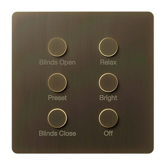
Alisse
English
P/N 041824 Rev. A
10/2021
Alisse Keypads
Installation Instructions
8 V- 30 mA
Please Read Before Installing
IEC PELV / SELV / NEC
®
HomeWorks
HW-NW-KP-S1
HW-NW-KP-S1-E
HW-NW-KP-S2
HW-NW-KP-S2-E
HW-NW-KP-S3
HW-NW-KP-S3-E
Included Components
Keypad Assembly
Wiring Harness
Use these instructions to install the model numbers listed above.
Important Notes
Install in accordance with all national and local electrical codes.
Lutron recommends that wallstations be installed by a
qualified electrician.
Do not connect high-voltage power to low-voltage terminals. Improper
wiring can result in personal injury or damage to the control or to
other equipment.
Environment: Ambient operating temperature: 32 °F to 104 °F
(0 °C to 40 °C), 0% to 90% humidity, non-condensing. Indoor use only.
Cleaning: For disinfecting keypad, please refer to app note:
http://www.lutron.com/TechnicalDocumentLibrary/048758_Cleaning_
Recommendations_for_Lutron_Products.pdf
Backboxes:
Square-style backbox dimensions: 2.95 in H × 2.95 in W × ≥ 1.4 in D
(75 mm H × 75 mm W × ≥ 35 mm D)
Round-style backbox dimensions: f 2.68 in × ≥ 1.4 in D
( f 68 mm × ≥ 35 mm D)
Please review Alisse Keypads - Round Backbox Installation
Best Practices Application Note #791 (048791) at www.lutron.com/Alisse
Base Unit Wiring
• The total length of wire on a wired QS link is not to exceed 2000 ft (610 m).
• Wiring may be in a daisy-chain, star, or T-tap configuration.
• See Alisse QS Keypad Base Unit Install at www.lutron.com/Alisse for reference.
System Programming: Programming and activation (addressing) must be
accomplished through the system software.
Engraving: Engraving must be specified when ordering the keypad.
See engraving.lutron.com/alisse for engraving details.
Customer Assistance:
U.S.A. / Canada: 1.844.LUTRON1 | Europe: +44.(0)20.7680.4481
Mexico: +1.888.235.2910 | Brazil: +55 (11) 3257-6745
Other Countries: +1.610.282.3800
www.lutron.com / support | forums.lutron.com
Lutron Electronics Co., Inc.
7200 Suter Road, Coopersburg, PA 18036-1299
Installation
!
1.
WARNING — Shock Hazard. May result in Serious Injury
or Death. Turn off power at the circuit breaker before installing
the unit.
Backbox
Class 2
Square Backbox
Round Backbox
Base Unit Adapters
S1: One & Two
S3: Three
R1: One & Two
Column
Column
Square Backbox
Square Backbox
*
Note: Square adapters are not compatible with round backboxes. Likewise, round adapters are not
compatible with square backboxes.
One & Two Column (Two Column Square Backbox shown)
One & Two Column Adapter Ring
Wiring Harness
Base Unit Mounting Screws (2)
(Included with square base unit)
Keypad Assembly
Three Column (Three Column Round Backbox shown)
Three Column Adapter Ring
Wiring Harness
Base Unit Mounting Screws (2)
(Included with the backbox)
Keypad Assembly
1
Note: Certain aspects of round box installations require special attention.
See Alisse Keypads - Round Backbox Installations Best Practices Application Note #791 (048791) at
www.lutron.com/Alisse
Note the orientation of the screws.
2
Lutron, HomeWorks, and Alisse are trademarks or registered trademarks of Lutron Electronics Co., Inc. in the US and/or other countries.
All other product names, logos, and brands are property of their respective owners. ©2015-2021 Lutron Electronics Co., Inc.
2. Remove the construction cover from the base unit (if present) by
pulling from the corner.
3. Connect the keypad to the base unit.
a. Connect one end of the wiring harness (provided with the keypad)
to the base unit.
b. Connect the other end of the wiring harness to the keypad.
Keypad to Base Unit Wiring
R3: Three
Column
Column
Round Backbox
Round Backbox
Backbox (Square)
Base Unit
2
IGNORE DETAILS A AND B
IGNORE DETAILS A AND B
DETAIL B
SCALE 2:1
DETAIL A
SCALE 2: I
4. Snap the keypad assembly onto the base unit, aligning the features
DETAIL B
SCALE 2:1
shown below in the keypad and the base unit. Do not pinch the wires.
DETAIL A
SCALE 2: I
Backbox (Round)
1
Base Unit
2
5. Turn on the power.
T
roubleshooting Guide
Symptom
Keypad LEDs do not change
when the button is pressed.
Keypad LEDs do not turn on.
Keypad LEDs scrolling
upward.
CCIs do not function
as intended.
Base unit button does not
function as intended.
Base unit LED flashing Green.
Base unit LED flashing Blue.
Base unit LED flashing Red.
Wiring Harness
Keypad does not sit flush to
the wall surface.
Keypad won't snap
onto adapter.
Returning Keypads to Factory Settings
Returning a keypad or base unit to its Factory Settings will remove the
keypad and base unit from the system and erase all programming.
1. Triple tap any button on the keypad or the base unit button. DO NOT
release after third tap.
2. Keep the button pressed on the third tap until all the LEDs start to flash
slowly (approximately 3 seconds).
3. Immediately release the button and triple tap the button again.
The LEDs on the keypad and the base unit will flash quickly.
The keypad has now been returned to Factory Settings.
Warranty:
http://www.lutron.com/TechnicalDocumentLibrary/043492.pdf
https://www.lutron.com/TechnicalDocumentLibrary/Intl_Warranty.pdf
Note: Contact your local Lutron representative for replacement parts
Replacement Adapters
NW-A-S1 (Square backbox one & two column adapter)
NW-A-S3 (Square backbox three column adapter)
NW-A-R1 (Round backbox one & two column adapter)
NW-A-R3 (Round backbox three column adapter)
Replacement Wiring Harness
NW-WH
FCC/IC Information
Please visit www.lutron.com/FCC
Possible Causes
• Miswire or loose connection of the keypad
to the base unit harness.
• Device programmed incorrectly.
• Miswire or loose connection of the keypad
to the base unit harness.
• Keypad damaged and not turning on.
• Miswire or loose connection at the wired
QS link.
• Miswire or loose connection at the wired
CCI link.
• Device programmed incorrectly.
• No loads connected to the same link as
the base unit. (Prior to programming, only
loads on the same link as the base unit will
toggle on / off.)
• Device programmed incorrectly.
• No communication with the QS processor.
• Device working properly.
• Device receiving updates from the
QS processor.
• No communication with the QS processor.
• Wrong adapter for backbox shape.
• Backbox is not mounted flush to the wall.
See Application Note #791 (P/N 048791).
• Adapter mounted upside down, ensure
adapter and keypad alignment features
correctly align. See Step 3 for reference.
• Incorrect adapter for the backbox shape used.
• Incorrect adapter for the number of
keypad columns.
• Backbox is not mounted flush to the wall.
See Application Note #791 (P/N 048791).
Advertisement
Table of Contents

Related Manuals for Lutron Electronics Alisse


Summary of Contents for Lutron Electronics Alisse
- Page 1 / support | forums.lutron.com Note the orientation of the screws. Lutron, HomeWorks, and Alisse are trademarks or registered trademarks of Lutron Electronics Co., Inc. in the US and/or other countries. Lutron Electronics Co., Inc. All other product names, logos, and brands are property of their respective owners. ©2015-2021 Lutron Electronics Co., Inc.
-
Page 2: Installation
| forums.lutron.com Notez l’orientation des vis. Lutron, HomeWorks et Alisse sont des marques commerciales ou déposées de Lutron Electronics Co., Inc. aux États-Unis et/ou dans d’autres pays. Lutron Electronics Co., Inc. Tous les autres noms de produits, logos et marques appartiennent à leurs propriétaires respectifs. ©2015-2021 Lutron Electronics Co., Inc. -
Page 3: Instalación
/ support | forums.lutron.com Tenga en cuenta la orientación de los tornillos. Lutron, HomeWorks y Alisse son marcas comerciales o marcas comerciales registradas de Lutron Electronics Co., Inc. en E.U.A. y/o en otros países. Lutron Electronics Co., Inc. Todos los demás nombres de productos, logotipos y marcas son de propiedad de sus respectivos poseedores. ©2015-2021 Lutron Electronics Co., Inc. - Page 4 | forums.lutron.com Observe a sentido de girar os parafusos. Lutron, HomeWorks e Alisse são marcas comerciais ou registradas da Lutron Electronics Co., Inc. nos EUA e em outros países. Lutron Electronics Co., Inc. Todos os nomes de produtos, logomarcas e marcas são proprietários. ©2015-2021 Lutron Electronics Co., Inc.
- Page 5 Ausrichtung der Schrauben beachten. Lutron Electronics Co., Inc. Lutron, HomeWorks und Alisse sind Marken oder eingetragene Marken der Lutron Electronics Co., Inc. in den USA bzw. in anderen Ländern. 7200 Suter Road, Coopersburg, PA 18036-1299, USA Alle anderen Produktnamen, Logos und Marken sind das Eigentum ihrer jeweiligen Inhaber. ©2015-2021 Lutron Electronics Co., Inc.
-
Page 6: Installazione
/ support | forums.lutron.com Si noti l’orientamento delle viti. Lutron, HomeWorks e Alisse sono marchi o marchi registrati di Lutron Electronics Co., Inc. negli Stati Uniti e/o in altri Paesi. Lutron Electronics Co., Inc. Tutti gli altri nomi di prodotto, loghi e marchi sono di proprietà dei rispettivi proprietari. ©2015-2021 Lutron Electronics Co., Inc. - Page 7 Onthoud de oriëntatie van de schroeven. Lutron Electronics Co., Inc. Lutron, HomeWorks en Alisse zijn handelsmerken of geregistreerde handelsmerken van Lutron Electronics Co., Inc. in de VS en/of andere landen. 7200 Suter Road, Coopersburg, PA 18036-1299, VS Alle andere productnamen, logo's en merken zijn eigendom van hun respectieve eigenaren. ©2015-2021 Lutron Electronics Co., Inc.
- Page 8 请参阅www.lutron.com/Alisse上的Alisse面板 - 圆形背盒安装最佳实践应用说明#791(048791) 5. 打开 电源。 墨西哥:+1.888.235.2910 | 巴西:+55(11( 3257-6745 注意螺钉的方向。 其他国家:+1.610.282.3800 www.lutron.com / support | forums.lutron.com Lutron、HomeWorks 及 Alisse 是位于美国和/或其他国家和地区的 Lutron Electronics Co., Inc. 的商标或注册商标。 Lutron Electronics Co., Inc. 所有其他产品名称、徽标和品牌均为其各自所有者的财产。©2015-2021 Lutron Electronics Co., Inc. 7200 Suter Road, Coopersburg, PA 18036-1299...
Need help?
Do you have a question about the Alisse and is the answer not in the manual?
Questions and answers