Emerson Rosemount 1057 Quick Start Manual
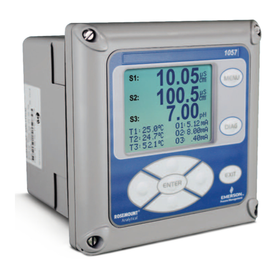
Triple channel transmitter
Hide thumbs
Also See for Rosemount 1057:
- Instruction manual (62 pages) ,
- Instruction manual (66 pages) ,
- Quick start manual (24 pages)

Related Manuals for Emerson Rosemount 1057


Summary of Contents for Emerson Rosemount 1057
- Page 1 Quick Start Guide 00825-0100-3157, Rev AC February 2022 ™ Rosemount 1057 Triple Channel Transmitter...
- Page 2 Intelligent Analyzer Reference Manual. Your instrument purchase from Emerson is one of the finest available for your particular application. These instruments have been designed and tested to meet many national and international standards. Experience indicates that its performance is directly related to the quality of the installation and knowledge of the user in operating and maintaining the instrument.
-
Page 3: Table Of Contents
Ensure that you have received the correct model and options from your purchase order. Verify that this Quick Start Guide covers your model and options. If it does not, call the Emerson Customer Care Center at +1 800 999 9307 to request the correct Quick Start Guide. - Page 4 Quick Start Guide February 2022 Emerson.com/Rosemount...
-
Page 5: First Steps
1. Inspect the shipping container. If it is damaged, contact the shipper immediately for instructions. 2. If there is no apparent damage, unpack the container. Be sure all items shown on the packing list are present. If items are missing, notify Emerson immediately. Dimensional drawings Panel mounting Note The front panel is hinged at the bottom. - Page 6 Quick Start Guide February 2022 Figure 1-2: Panel mount, side view A. Panel mount gasket B. Four mounting brackets and screws provided with transmitter C. Panels supplied by others. Maximum thickness: 0.375 in (9.52 mm) Emerson.com/Rosemount...
- Page 7 February 2022 Quick Start Guide Figure 1-3: Panel mount, bottom view A. Conduit openings Figure 1-4: Panel cut-out A. Maximum radius Quick Start Guide...
- Page 8 Quick Start Guide February 2022 Wall mounting Figure 1-5: Wall Mount, front view A. Four cover screws Emerson.com/Rosemount...
- Page 9 February 2022 Quick Start Guide Figure 1-6: Wall mount, side view Quick Start Guide...
- Page 10 Quick Start Guide February 2022 Pipe mounting Figure 1-7: Pipe mount, side view A. 2 in (51 mm) pipe supplied by customer Emerson.com/Rosemount...
- Page 11 February 2022 Quick Start Guide Figure 1-8: Pipe mount, bottom view A. Front panel B. Panel and pipe mount enclosure C. Conduit openings D. 2 in (51 mm) pipe mount bracket E. Two sets U-bolts for 2 in (51 mm) pipe in kit: PN 23820-00 Quick Start Guide...
-
Page 12: General Installation Information
3. Keep the transmitter and sensor wiring at least 1 ft (0.30 m) from high voltage conductors. Be sure there is easy access to the transmitter. 4. The transmitter is suitable for panel, pipe, or surface mounting. Refer Dimensional drawings. Emerson.com/Rosemount... -
Page 13: Wiring
3.1.3 Alarm relays Emerson supplies four alarm relays with the switching power supply (85 to 264 Vac, 03 order code) and the 24 Vdc power supply (20 - 30 Vdc, 02 order code). You can use all relays for process measurement(s) or temperature. - Page 14 Preparing conduit openings There are six conduit openings in all configurations of the transmitter. Note Emerson fits four of the openings with plugs upon shipment. Figure 3-1: Conduit openings A. Front panel/keypad B. Power leads C. Alarm relay leads D.
- Page 15 Power, output, and sensor connections 3.3.1 Power wiring Emerson offers two power supplies for the Rosemount 1057: 1. 24 Vdc (20-30 V) power supply (02 ordering code) 2. 85-265 Vac switching power supply (03 ordering code) AC mains (115 or 230 V) leads and 24 Vdc leads are wired to the power supply board, which is mounted vertically on the left side of the main enclosure cavity.
- Page 16 Vdc inputs. Four programmable alarm relays are included. Figure 3-3: Switching AC power supply (03 ordering code) This power supply automatically detects AC line conditions and switches to the proper line voltage and line frequency. Four programmable relays are included. Emerson.com/Rosemount...
- Page 17 Quick Start Guide 3.3.2 Alarm relay wiring Emerson supplies four alarm relays with the switching power supply (85 to 265 Vac, 03 order code) and the 24 Vdc power supply (20-30 Vdc, 02 order code). Wire the relay leads on each of the independent relays to the correct position on the power supply board using the printed lead markings (NO/ Normally open, NC/Normally closed, or Com/Common) on the board.
- Page 18 1. Wire TB5/anode and cathode to the anode and cathode terminals. 2. Wire TB3/RTD to the return, sense, and RTD in terminals. 3. Wire TB2/solution ground to the solution ground terminal. For recommended wire entry points, see Figure 3-1. Emerson.com/Rosemount...
-
Page 19: Navigating The Display
February 2022 Quick Start Guide Navigating the display User interface The transmitter has a large display which shows the three live measurement readouts and up to six additional process variables or diagnostic parameters concurrently. The display is back-lit, and the you can customize the format to meet your requirements. - Page 20 Selection keys are used to: 1. Select items on the menu screens. 2. Scroll up and down the menu lists. 3. Enter or edit numeric values. 4. Move the cursor to the right or left. 5. Select measurement units during operation. Emerson.com/Rosemount...
- Page 21 February 2022 Quick Start Guide Main display The transmitter displays one, two, or three primary measurement values, up to six secondary measurement values, a fault and warning banner, and alarm relay flags. Process measurements Three process variables are displayed if three signal boards are installed. One process variable and process temperature are displayed if one signal board is installed with one sensor.
- Page 22 You can elect to disable the display of temperature in the center display area using the Main Format function. See Figure 4-1 to guide you through programming the main display to select process parameters and diagnostics of your choice. Emerson.com/Rosemount...
- Page 23 February 2022 Quick Start Guide Figure 4-1: Formatting the main display Menu system The transmitter uses a scroll and select menu system. Press MENU at any time to open the top-level menu, including Calibrate, Hold, Program, and Display functions. To find a menu item, scroll with the Up and Down keys until the item is highlighted.
- Page 24 This conveniently allows display of the live values during important calibration and programming operations. Menu screens time out after two minutes and return to the main display. Emerson.com/Rosemount...
-
Page 25: Start Up Transmitter
February 2022 Quick Start Guide Start up transmitter Procedure 1. Wire sensor(s) to the signal boards. Wiring for wiring instructions. Refer to the sensor Quick Start Guide for additional details. Make current output, alarm relay, and power connections. 2. Once connections are secured and verified, close the panel and apply power to the transmitter. - Page 26 After the last step, the main display appears. The outputs are assigned to default values. 4. To change output and temperature-related settings, go to the main menu and choose Program. Follow the prompts. For a general guide to the Program menu, see Figure 5-2 Emerson.com/Rosemount...
- Page 27 Quick Start Guide Figure 5-2: 1057 Menu Tree 5. To return the transmitter to the factory default settings, choose Reset Analyzer under the Program menu. Please call the Emerson Customer Support Center at 1-800-999-9307 if you need further support. Quick Start Guide...
-
Page 28: Approvals
Approvals Pollution degree Installation category Altitude 6,561.7 ft (2,000 m) Humidity 80 percent to temperatures up to 88 °F (31 °C) decreasing linearly to 50 percent relative humidity at 104 °F (40 °C). Maximum 80 percent relative humidity, non-condensing. Emerson.com/Rosemount... -
Page 29: Product Certifications
A copy of the EU Declaration of Conformity can be found at the end of this guide. The most recent revision of the EU Declaration of Conformity can be found at Emerson.com/Rosemount. Ordinary location certification As standard, the transmitter has been examined and tested to determine... - Page 30 Standard 50E, 3rd edition, UL 61010-1, 3rd edition Markings Class I, Division 2, Groups A, B, C, and D; Class II, Division 2, Groups E, F, and G; Class III Maximum ambient 55 °C; temperature code T4A; enclosure Type 4X; IP66 Emerson.com/Rosemount...
-
Page 31: Eu Declaration Of Conformity
February 2022 Quick Start Guide EU Declaration of Conformity Quick Start Guide... - Page 32 Quick Start Guide February 2022 Emerson.com/Rosemount...
-
Page 33: China Rohs Table
February 2022 Quick Start Guide China RoHS table Quick Start Guide... - Page 34 Quick Start Guide February 2022 Emerson.com/Rosemount...
- Page 35 February 2022 Quick Start Guide Quick Start Guide...
- Page 36 For more information: Emerson.com © 2022 Emerson. All rights reserved. Emerson Terms and Conditions of Sale are available upon request. The Emerson logo is a trademark and service mark of Emerson Electric Co. Rosemount is a mark of one of the Emerson family of companies.
Need help?
Do you have a question about the Rosemount 1057 and is the answer not in the manual?
Questions and answers