Table of Contents
Advertisement
Quick Links
Advertisement
Table of Contents
Troubleshooting

Related Manuals for IEI Technology HTB-210-Q470


Summary of Contents for IEI Technology HTB-210-Q470
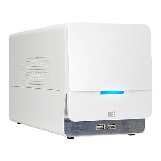
- Page 1 HTB-210-Q470 Embedded System HTB-210-Q470 Box PC MODEL: MODEL: HTB-210-Q470 ® Embedded System Supports Intel Core™ i5-10500TE CPU, DDR4, RS-232/422/485, 2.5GbE LAN, USB 3.2 Gen 1, PCIe x16/x4, M.2, SATA 6Gb/s, HDMI, DP and RoHS User Manual Page i Rev. 1.00 – October 29, 2021...
- Page 2 HTB-210-Q470 Embedded System Revision Date Version Changes October 29, 2021 1.00 Initial release Page ii...
- Page 3 HTB-210-Q470 Embedded System Copyright COPYRIGHT NOTICE The information in this document is subject to change without prior notice in order to improve reliability, design and function and does not represent a commitment on the part of the manufacturer. In no event will the manufacturer be liable for direct, indirect, special, incidental, or consequential damages arising out of the use or inability to use the product or documentation, even if advised of the possibility of such damages.
- Page 4 HTB-210-Q470 Embedded System Manual Conventions WARNING Warnings appear where overlooked details may cause damage to the equipment or result in personal injury. Warnings should be taken seriously. CAUTION Cautionary messages should be heeded to help reduce the chance of losing data or damaging the product.
-
Page 5: Table Of Contents
HTB-210-Q470 Embedded System Table of Contents 1 INTRODUCTION ......................1 1.1 O ........................2 VERVIEW 1.2 F ........................2 EATURES 1.3 F ......................3 RONT ANEL 1.4 R ......................3 ANEL 1.5 B ......................4 OTTOM ANEL 1.6 T ..................4... - Page 6 HTB-210-Q470 Embedded System 4.1.1 Starting Setup ....................26 4.1.2 Using Setup ...................... 26 4.1.3 Getting Help ..................... 27 4.1.4 Unable to Reboot after Configuration Changes ..........27 4.1.5 BIOS Menu Bar ....................27 4.2 M ........................27 4.3 A ....................... 29 DVANCED 4.3.1 CPU Configuration ..................
- Page 7 HTB-210-Q470 Embedded System 5.1 S ................. 64 YSTEM AINTENANCE VERVIEW 5.2 S ..................64 YSTEM ROUBLESHOOTING 5.2.1 The System Doesn’t Turn On ................64 5.2.2 The System Doesn’t Boot Up ................65 5.2.3 More Troubleshooting ..................65 5.3 C ..............66...
- Page 8 HTB-210-Q470 Embedded System A REGULATORY COMPLIANCE ................80 B SAFETY PRECAUTIONS ..................85 B.1 S ..................... 86 AFETY RECAUTIONS B.1.1 General Safety Precautions ................86 B.1.2 Anti-static Precautions ..................87 B.1.3 Product Disposal ..................... 88 B.1.4 Classification ....................89 B.2 M ............
- Page 9 HTB-210-Q470 Embedded System List of Figures Figure 1-1: HTB-210-Q470 Embedded System ................2 Figure 1-2: Front Panel ........................3 Figure 1-3: Rear Panel ........................3 Figure 1-4: Bottom Panel ....................... 4 Figure 1-5: Dimensions (mm) ......................6 Figure 3-1: Top Cover Retention Screws ...................13 Figure 3-2: HDD Access Panel Retention Screws ..............14...
- Page 10 HTB-210-Q470 Embedded System List of Tables Table 1-1: Technical Specifications ....................5 Table 2-1: Package List ........................9 Table 2-2: Optional Item ......................... 9 Table 3-1: RS-232/422/485 Serial Port Pinouts ................20 Table 4-1: BIOS Options and Configured USB Ports ..............55 Table 6-1: Peripheral Interface Connectors ................70...
- Page 11 HTB-210-Q470 Embedded System Page xi...
- Page 12 HTB-210-Q470 Embedded System List of BIOS Menus BIOS Menu 1: Main ........................28 BIOS Menu 2: Advanced ......................29 BIOS Menu 3: CPU Configuration ....................30 BIOS Menu 4: PCH-FW Configuration ..................32 BIOS Menu 5: PTT Configuration ....................33 BIOS Menu 6: Trusted Computing ....................34 BIOS Menu 7: ACPI Configuration ....................35...
-
Page 13: Introduction
HTB-210-Q470 Embedded System Chapter Introduction Page 1... -
Page 14: Overview
It is designed for applications that require reliable operating and easy maintenance features. The HTB-210-Q470 provides one PCIe x16 slot and one PCIe x4 slot for building AI applications by installing accelerator cards. Its I/O interfaces include two USB 3.2 Gen 1 ports, two USB 2.0 ports, two 2.5GbE, one serial port, one DP and one HDMI. -
Page 15: Front Panel
Figure 1-2: Front Panel 1.4 Rear Panel The rear panel of the HTB-210-Q470 provides access to the following external I/O 6 9 2 H 6 9 2 H 5 6 9 H connectors, button and expansion slots as shown in Figure 1-3. -
Page 16: Bottom Panel
HTB-210-Q470 Embedded System 1.5 Bottom Panel The bottom panel has a HDD access panel for HDD installation or replacement. Figure 1-4: Bottom Panel 1.6 Technical Specifications The specifications for the Intel based embedded systems are listed below. HTB-210-Q470 Support Intel ®... -
Page 17: Table 1-1: Technical Specifications
HTB-210-Q470 Embedded System Storage 1 x 2.5" SATA 6Gb/s HDD/SSD bay Expansion 1 x PCIe 3.0 x16 slot 1 x PCIe 3.0 x4 slot 1 x M.2 A-key 2230 slot (PCIe x2 and USB 2.0) 1 x M.2 M-key 2280 slot (PCIe x4 and SATA) -
Page 18: Dimensions
HTB-210-Q470 Embedded System 1.7 Dimensions The dimensions of the HTB-210-Q470 are shown in F igure 1-5. 6 8 8 H 6 8 8 H 5 6 7 H Figure 1-5: Dimensions (mm) Page 6... -
Page 19: Unpacking
HTB-210-Q470 Embedded System Chapter Unpacking Page 7... -
Page 20: Unpacking
Contact the IEI reseller or vendor the HTB-210-Q470 was purchased from or contact an IEI sales representative directly by sending an email to ales@ieiworld.com. 3 2 6 H 3 7 8 H The HTB-210-Q470 embedded system is shipped with the following components: Page 8... -
Page 21: Optional Items
HTB-210-Q470 Embedded System Quantity Item Image HTB-210-Q470 embedded system Power cord 180 W power adapter Screws (M3*4) for HDD installation Table 2-1: Package List 2.3 Optional Items The following is the optional component which may be separately purchased: Item and Part Number... -
Page 22: Installation
HTB-210-Q470 Embedded System Chapter Installation Page 10... -
Page 23: Anti-Static Precautions
Electrostatic discharge (ESD) can cause serious damage to electronic components, including the HTB-210-Q470. Dry climates are especially susceptible to ESD. It is therefore critical that whenever the HTB-210-Q470 is accessed internally, or any other electrical component is handled, the following anti-static precautions are strictly adhered ... -
Page 24: Installation Precautions
the HTB-210-Q470. The HTB-210-Q470’s cooling vents must not be obstructed by any objects. Blocking the vents can cause overheating of the HTB-210-Q470. Leave at least 5 cm of clearance around the HTB-210-Q470 to prevent overheating. Grounding: The HTB-210-Q470 should be properly grounded. The voltage feeds must not be overloaded. -
Page 25: Opening Top Cover
HTB-210-Q470 Embedded System 3.3 Opening Top Cover Before the internal components can be installed, the top cover must be opened. To open the top cover, please follow the steps below: Step 1: Remove the top cover retention screws. The top cover is secured to the chassis with 3 retention screws. -
Page 26: Hdd Installation
HTB-210-Q470 Embedded System 3.4 HDD Installation The HTB-210-Q470 has one 2.5" HDD bay inside the bottom of the system. To install an HDD, follow the steps below. Step 1: Turn over the system. Locate the HDD access panel. Loosen the four retention screws and remove the panel. -
Page 27: Figure 3-4: Inserting The Hdd
HTB-210-Q470 Embedded System Figure 3-4: Inserting the HDD Step 4: Insert the HDD bracket in the chassis. Slide the HDD bracket to connect the HDD to the SATA connector. Secure the HDD bracket by installing the two retention screws previously removed. -
Page 28: Module Installation
HTB-210-Q470 Embedded System 3.5 M.2 Module Installation The HTB-210-Q470 has one M.2 M-key slot for M.2 2280 module and one M.2 A-key slot for M.2 2230 module. To install M.2 modules into the HTB-210-Q470, follow the steps below. Step 1: Remove the top cover from the HTB-210-Q470. -
Page 29: Figure 3-7: Removing The M.2 Module Retention Screw
HTB-210-Q470 Embedded System Step 3: Remove the on-board retention screw as shown in Figure 3-7. Figure 3-7: Removing the M.2 Module Retention Screw Step 4: Line up the notch on the card with the notch on the slot. Slide the PCIe Mini card into the socket at an angle of about 20º... -
Page 30: Expansion Card Installation
HTB-210-Q470 Embedded System 3.6 Expansion Card Installation The HTB-210-Q470 supports one PCIe 3.0 x16 slot and one PCIe 3.0 x4 slot. To install an expansion card, follow the steps below. Step 1: Remove the top cover. See Section 3.3 above. -
Page 31: Clear Cmos
HTB-210-Q470 Embedded System 3.7 Clear CMOS If the HTB-210-Q470 fails to boot due to improper BIOS settings, the clear CMOS button clears the CMOS data and resets the system BIOS information. To do this, remove the system top cover first (see Section 3.3). Locate the clear CMOS button and push the button for three seconds, then restart the system. -
Page 32: Rs-232/422/485 Serial Device Connection
HTB-210-Q470 Embedded System 3.8 RS-232/422/485 Serial Device Connection The HTB-210-Q470 series has one RS-232/422/484 port (COM1) on the rear panel. The pinouts of the serial port are listed below. The default setting for COM1 is set to RS-232. To configure the COM port mode, change the BIOS options in Advanced ... -
Page 33: Power-On Procedure
HTB-210-Q470 Embedded System 3.9 Power-On Procedure 3.9.1 Installation Checklist WARNING: Make sure a power supply with the correct input voltage is being fed into the system. Incorrect voltages applied to the system may cause damage to the internal electronic components and may also cause injury to the user. -
Page 34: Figure 3-12: Power Button And Power Led
Ensure to connect the power cord to a socket-outlet with earthing connection. Step 2: Connect the power adapter to the power connector of the HTB-210-Q470. Step 3: Short-press the power button, and the power LED on the front panel will light on in blue (Figure 3-12). -
Page 35: Available Drivers
HTB-210-Q470 Embedded System 3.10 Available Drivers All the drivers for the HTB-210-Q470 are available on IEI Resource Download Center (https://download.ieiworld.com). Type HTB-210-Q470 and press Enter to find all the relevant software, utilities, and documentation. Figure 3-13: IEI Resource Download Center 3.10.1 Driver Download... - Page 36 HTB-210-Q470 Embedded System Step 3: Click the driver file name on the page and you will be prompted with the following window. You can download the entire ISO file ( ), or click the small arrow to find an individual driver and click the file name to download (...
-
Page 37: Bios
HTB-210-Q470 Embedded System Chapter BIOS Page 25... -
Page 38: Introduction
HTB-210-Q470 Embedded System 4.1 Introduction The BIOS is programmed onto the BIOS chip. The BIOS setup program allows changes to certain system settings. This chapter outlines the options that can be changed. NOTE: Some of the BIOS options may vary throughout the life cycle of the product and are subject to change without prior notice. -
Page 39: Getting Help
HTB-210-Q470 Embedded System Function Main Menu – Quit and not save changes into CMOS Status Page Setup Menu and Option Page Setup Menu -- Exit current page and return to Main Menu General help, only for Status Page Setup Menu and Option Page... -
Page 40: Bios Menu 1: Main
HTB-210-Q470 Embedded System The Main BIOS menu (BIOS Menu 1) appears when the BIOS Setup program is entered. The Main menu gives an overview of the basic system information. Aptio Setup – AMI Main Advanced Chipset Security Boot Save & Exit BIOS Information Set the Date. -
Page 41: Advanced
HTB-210-Q470 Embedded System System Date [xx/xx/xx] Use the System Date option to set the system date. Manually enter the day, month and year. System Time [xx:xx:xx] Use the System Time option to set the system time. Manually enter the hours, minutes and seconds. -
Page 42: Bios Menu 3: Cpu Configuration
HTB-210-Q470 Embedded System Use the CPU Configuration menu (BIOS Menu 3) to view detailed CPU specifications or enable the Intel Virtualization Technology. Aptio Setup – AMI Advanced CPU Configuration When enabled, a VMM can utilize the additional Type Intel(R) Core(TM) hardware capabilities i5-10500TE CPU @ 2.30GHz... - Page 43 HTB-210-Q470 Embedded System Enable all cores in the processor package. EFAULT Enable one core in the processor package. Enable two cores in the processor package. Enable three cores in the processor package. Enable four cores in the processor package.
-
Page 44: Pch-Fw Configuration
HTB-210-Q470 Embedded System 4.3.2 PCH-FW Configuration The PCH-FW Configuration menu (BIOS Menu 4) allows Intel ® Active Management Technology (AMT) options to be configured. Aptio Setup – AMI Advanced Unconfigure ME [Disabled] Unconfigure ME with resetting MEBx password to > PTT Configuration default. -
Page 45: Ptt Configuration
HTB-210-Q470 Embedded System 4.3.2.1 PTT Configuration Use the PTT Configuration menu (BIOS Menu 5) to configure settings related to the Trusted Platform Module (TPM). Aptio Setup – AMI Advanced PTT Capability / State Select TPM device: PTT or dTPM. PTT- Enables PTT in... -
Page 46: Trusted Computing
HTB-210-Q470 Embedded System 4.3.3 Trusted Computing Use the Trusted Computing menu (BIOS Menu 6) to configure settings related to the Trusted Computing Group (TCG) Trusted Platform Module (TPM). Aptio Setup – AMI Advanced Configuration Enables or Disables BIOS Security Device Support... -
Page 47: Acpi Settings
HTB-210-Q470 Embedded System 4.3.4 ACPI Settings The ACPI Settings menu (BIOS Menu 7) configures the Advanced Configuration and Power Interface (ACPI) options. Aptio Setup – AMI Advanced ACPI Settings Select the highest ACPI sleep state the system ACPI Sleep State... -
Page 48: F81804 Super Io Configuration
HTB-210-Q470 Embedded System 4.3.5 F81804 Super IO Configuration Use the F81804 Super IO Configuration menu (BIOS Menu 8) to set or change the configurations for the serial ports and parallel port. Aptio Setup – AMI Advanced F81804 Super IO Configuration... -
Page 49: Serial Port 1 Configuration
HTB-210-Q470 Embedded System 4.3.5.1 Serial Port 1 Configuration Use the Serial Port 1 Configuration menu (BIOS Menu 9) to configure the serial port 1. Aptio Setup – AMI Advanced Serial Port 1 Configuration Enable or Disable Serial Port (COM) Serial Port... -
Page 50: Iwdd H/W Monitor
HTB-210-Q470 Embedded System 4.3.6 iWDD H/W Monitor The iWDD H/W Monitor menu (BIOS Menu 10) contains the fan configuration submenu, and displays operating temperature, fan speeds and system voltages. Aptio Setup – AMI Advanced PC Health Status Smart Fan Mode Select CPU temperature : +28ºC... -
Page 51: Smart Fan Mode Configuration
HTB-210-Q470 Embedded System +12V +DDR +5VSB +3.3V +3.3VSB 4.3.6.1 Smart Fan Mode Configuration Use the Smart Fan Mode Configuration submenu (BIOS Menu 11) to configure fan speed settings. Aptio Setup – AMI Advanced Smart Fan Mode Configuration Smart Fan Mode Select... - Page 52 HTB-210-Q470 Embedded System The fan adjusts its speed using these Auto Mode EFAULT settings: Auto mode fan start temperature Auto mode fan off temperature Auto mode fan start PWM Auto mode fan slope PWM Auto mode fan start temperature [40]...
- Page 53 HTB-210-Q470 Embedded System change to be lowest. To set a value, select the Auto mode fan off temperature option and enter a decimal number between 1 and 100. Auto mode fan start PWM [40] Auto mode start option only CPU_FAN1/SYS_FAN1/SYS_FAN2 Smart Fan control option is set to Auto Mode.
-
Page 54: Rtc Wake Settings
HTB-210-Q470 Embedded System 4.3.7 RTC Wake Settings The RTC Wake Settings menu (BIOS Menu 12) enables the system to wake at the specified time. Aptio Setup – AMI Advanced Wake system with Fixed Time [Disabled] Enable or disable System wake on alarm event. When... -
Page 55: Serial Port Console Redirection
HTB-210-Q470 Embedded System Wake up minute Wake up second After setting the alarm, the computer turns itself on from a suspend state when the alarm goes off. 4.3.8 Serial Port Console Redirection The Serial Port Console Redirection menu (BIOS Menu 13) allows the console redirection options to be configured. - Page 56 HTB-210-Q470 Embedded System Terminal Type [ANSI] Use the Terminal Type option to specify the remote terminal type. VT100 The target terminal type is VT100 VT100+ The target terminal type is VT100+ VT-UTF8 The target terminal type is VT-UTF8 ...
-
Page 57: Usb Configuration
HTB-210-Q470 Embedded System The parity bit is 0 if the number of ones in the data bits is odd. Mark The parity bit is always 1. This option does not provide error detection. Space The parity bit is always 0. This option does not provide error detection. -
Page 58: Network Stack Configuration
HTB-210-Q470 Embedded System Legacy USB Support [Enabled] Use the Legacy USB Support BIOS option to enable USB mouse and USB keyboard support. Normally if this option is not enabled, any attached USB mouse or USB keyboard does not become available until a USB compatible operating system is fully booted with all USB drivers loaded. -
Page 59: Nvme Configuration
HTB-210-Q470 Embedded System Network Stack [Disabled] Use the Network Stack BIOS option to enable or disable UEFI network stack. Disabled UEFI network stack disabled EFAULT Enabled UEFI network stack enabled 4.3.11 NVMe Configuration Use the NVMe Configuration (BIOS Menu 16) menu to display the NVMe controller and device information. -
Page 60: Chipset
HTB-210-Q470 Embedded System 4.4 Chipset Use the Chipset menu (BIOS Menu 17) to access the PCH IO and System Agent (SA) configuration menus. WARNING! Setting the wrong values for the Chipset BIOS selections in the Chipset BIOS menu may cause the system to malfunction. -
Page 61: System Agent (Sa) Configuration
HTB-210-Q470 Embedded System 4.4.1 System Agent (SA) Configuration Use the System Agent (SA) Configuration menu (BIOS Menu 18) to configure the System Agent (SA) parameters. Aptio Setup – AMI Chipset System Agent (SA) Configuration VT-d capability VT-d Supported VT-d [Disabled] --------------------- : Select Screen... -
Page 62: Memory Configuration
HTB-210-Q470 Embedded System 4.4.1.1 Memory Configuration Use the Memory Configuration submenu (BIOS Menu 19) to view memory information. Aptio Setup – AMI Chipset Memory Configuration CHA_DIMM0# Populated & Enabled Size 16384 MB (DDR4) --------------------- Number of Ranks : Select Screen... - Page 63 HTB-210-Q470 Embedded System Primary Display [Auto] Use the Primary Display option to select the display device used by the system when it boots. Configuration options are listed below. Auto EFAULT IGFX PCIE Internal Graphics [Enabled] Use the Internal Graphics option to keep IGFX enabled basing on the setup options.
-
Page 64: Peg Port Configuration
HTB-210-Q470 Embedded System 4.4.1.3 PEG Port Configuration Aptio Setup – AMI Chipset PEG Port Configuration Select PEG Port Link Width as x16 or 2x8 or 1x8 PCIEX8_1 Not Present & 2x4 configuration. Enable Root Port [Enabled] Max Link Speed [Auto]... -
Page 65: Pch-Io Configuration
HTB-210-Q470 Embedded System Disables to detect if a non-compliance PCI Disabled EFAULT Express device is connected to the PCI Express slot. Enabled Enables to detect if a non-compliance PCI Express device is connected to the PCI Express slot. - Page 66 HTB-210-Q470 Embedded System Power Saving Function(ERP) [Disabled] Use the Power Saving Function(ERP) BIOS option to enable or disable the power saving function. Disabled Power saving function is disabled. EFAULT Power saving function is enabled. It will reduce power Enabled consumption when the system is off.
-
Page 67: Pci Express Configuration
HTB-210-Q470 Embedded System BIOS Options Configured USB Ports External USB 3.2 Gen 1 port (rear panel) USB Power SW1 External USB 3.2 Gen 1 port (rear panel) External USB 2.0 ports (front panel) USB Power SW2 External USB 2.0 ports (front panel) Table 4-1: BIOS Options and Configured USB Ports 4.4.2.1 PCI Express Configuration... -
Page 68: Bios Menu 24: Pci Express Port Submenu
HTB-210-Q470 Embedded System 4.4.2.1.1 PCI Express Port Aptio Setup – AMI Advanced PCIe Speed [Auto] Select PCI Express port Detect Non-Compliance Device [Disabled] speed. --------------------- : Select Screen : Select Item Enter: Select +/-: Change Opt. General Help Previous Values Optimized Defaults Save &... -
Page 69: Sata And Rst Configuration
HTB-210-Q470 Embedded System 4.4.2.2 SATA and RST Configuration Use the SATA and RST Configuration menu (BIOS Menu 25) to change and/or set the configuration of the SATA devices installed in the system. Aptio Setup – AMI Chipset SATA And RST Configuration Enable or disable SATA Device. -
Page 70: Hd Audio Configuration
HTB-210-Q470 Embedded System Hot Plug [Disabled] Use the Hot Plug option to designate the correspondent SATA port as hot-pluggable. Disabled EFAULT Disables the hot-pluggable function of the SATA port. Enabled Designates the SATA port as hot-pluggable. 4.4.2.3 HD Audio Configuration Use the HD Audio Configuration menu (BIOS Menu 26) to configure the PCH Azalia settings. -
Page 71: Security
HTB-210-Q470 Embedded System 4.5 Security Use the Security menu (BIOS Menu 27) to set system and user passwords. Aptio Setup – AMI Main Advanced Chipset Security Boot Save & Exit Password Description Set Administrator Password If ONLY the Administrator’s password is set, then this only limits access to Setup and is only asked for when entering Setup. -
Page 72: Boot
HTB-210-Q470 Embedded System 4.6 Boot Use the Boot menu (BIOS Menu 28) to configure system boot options. Aptio Setup – AMI Main Advanced Chipset Security Boot Save & Exit Boot Configuration Select the keyboard Bootup NumLock State [On] NumLock state... - Page 73 HTB-210-Q470 Embedded System Quiet Boot [Enabled] Use the Quiet Boot BIOS option to select the screen display when the system boots. Disabled Normal POST messages displayed Enabled OEM Logo displayed instead of POST messages EFAULT Option ROM Messages [Force BIOS] Use the Option ROM Messages option to set the Option ROM display mode.
-
Page 74: Save & Exit
HTB-210-Q470 Embedded System 4.7 Save & Exit Use the Safe & Exit menu (BIOS Menu 29) to load default BIOS values, optimal failsafe values and to save configuration changes. Aptio Setup – AMI Main Advanced Chipset Security Boot Save & Exit... -
Page 75: Troubleshooting And Maintenance
HTB-210-Q470 Embedded System Chapter Troubleshooting and Maintenance Page 63... -
Page 76: System Maintenance Overview
Failure to follow these instructions may lead to personal injury and system damage. To preserve the working integrity of the HTB-210-Q470 embedded system, the system must be properly maintained. If embedded system components need replacement, the proper maintenance procedures must be followed to ensure the system can continue to operate normally. -
Page 77: The System Doesn't Boot Up
If all troubleshooting measures have been taken and the system still fails to start, contact the IEI reseller or vendor you purchased the HTB-210-Q470 from or contact an IEI sales representative directly. To contact an IEI sales representative, please send an email to ales@ieiworld.com. -
Page 78: Component Replacement Procedure
If any other components fail or need replacement, contact the IEI reseller or vendor you purchased the HTB-210-Q470 from or contact an IEI sales representative directly. To contact an IEI sales representative, please send an email to ales@ieiworld.com. -
Page 79: Figure 5-1: So-Dimm Location
HTB-210-Q470 Embedded System Figure 5-1: SO-DIMM Location Step 3: Push both handles outward. The memory module is ejected by a mechanism in the socket. Remove the SO-DIMM. Step 4: Align the new SO-DIMM with the socket. The SO-DIMM must be oriented in... -
Page 80: Interface Connectors
HTB-210-Q470 Embedded System Chapter Interface Connectors Page 68... -
Page 81: Peripheral Interface Connectors
HTB-210-Q470 Embedded System 6.1 Peripheral Interface Connectors The connector locations of the system motherboard (HPCIE-C236) are shown in Table 6-1. Figure 6-1: Main Board Layout Diagrams Page 69... -
Page 82: Internal Peripheral Connectors
HTB-210-Q470 Embedded System 6.2 Internal Peripheral Connectors Internal peripheral connectors on the motherboard and are only accessible when the motherboard is outside of the chassis. The table below shows a list of the connectors on the motherboard. Connector Type Label... -
Page 83: Atx Power Connector (Cpu12V1)
HTB-210-Q470 Embedded System 6.2.1 +12V ATX Power Connector (CPU12V1) PIN NO. DESCRIPTION PIN NO. DESCRIPTION +12V +12V Table 6-2: +12V ATX Power Connector (CPU12V1 Pinouts 6.2.2 Audio Kit Connector (J_AUDIO1) PIN NO. DESCRIPTION PIN NO. DESCRIPTION HDA_SYNC HDA_BIT_CLK HDA_SDOUT HDA_SPKR... -
Page 84: Chassis Intrusion Connector (Chassis1)
HTB-210-Q470 Embedded System 6.2.5 Chassis Intrusion Connector (CHASSIS1) PIN NO. DESCRIPTION +3.3VSB CHASSIS OPEN Table 6-6: Chassis Intrusion Connector (CHASSIS1) Pinouts 6.2.6 Debug Port Connector (DBG_PORT1) PIN NO. DESCRIPTION PIN NO. DESCRIPTION SMCLK_EC SMDAT_EC PLTRST_N Table 6-7: Debug Port Connector (DBG_PORT1) Pinouts 6.2.7 Digital I/O Connector (DIO1) -
Page 85: Front Panel Connector (F_Panel1)
HTB-210-Q470 Embedded System 6.2.9 Front Panel Connector (F_PANEL1) FUNCTION DESCRIPTION FUNCTION DESCRIPTION Power LED PWR_LED+ Power Button PWR_BTN+ PWR_LED+ PWR_BTN- PWR_LED- HDD LED HDD_LED+ Reset RESET+ HDD_LED- RESET- Table 6-10: Front Panel Connector (F_PANEL1) Pinouts 6.2.10 I C Connector (I2C1) PIN NO. -
Page 86: Sata Connectors (S_Ata1, S_Ata2)
HTB-210-Q470 Embedded System 6.2.12 SATA Connectors (S_ATA1, S_ATA2) Description Table 6-13: SATA Connectors (S_ATA1, S_ATA2) Pinouts 6.2.13 SMBus Connector (SMB1) PIN NO. DESCRIPTION SMBus Data SMBus CLK Table 6-14: SMBus Connector (SMB1) Pinouts 6.2.14 USB 2.0 Connector (USB2) PIN NO. -
Page 87: Tpm Connector (Tpm1)
HTB-210-Q470 Embedded System 6.2.15 TPM Connector (TPM1) PIN NO. DESCRIPTION PIN NO. DESCRIPTION SPI_TPM_CS0# SPI_TPM_GPIO SPI_TPM_CS1# +3.3V SPI_TPM_CLK SPI_IO2 SPI_IO3 SPI_TPM_SO SPI_TPM_HOLD- SPI_TPM_SI SPI_TPM_CS2- SPI_TPM_WP SERIRQ_TPM SPI_TPM_PIRQ +3.3V_SPI PCIE_RST- +3.3V_SPI Table 6-16: TPM Connector (TPM1) Pinouts 6.3 External Interface Panel Connectors The table below lists the connectors on the external I/O panel. -
Page 88: Ethernet Connectors (Lan1)
HTB-210-Q470 Embedded System 6.3.1 Ethernet Connectors (LAN1) PIN NO. DESCRIPTION PIN NO. DESCRIPTION MDI0+ MDI2+ MDI0- MDI2- MDI1+ MDI3+ MDI1- MDI3- Table 6-18: Ethernet Connectors (LAN1) Pinouts Description Description on: linked off: 10/100 Mb/s blinking: data is being sent/received orange: 1 Gb/s green: 2.5 Gb/s... -
Page 89: Usb/Dp Connector (Usb_C1)
HTB-210-Q470 Embedded System 6.3.3 USB/DP Connector (USB_C1) PIN NO. DESCRIPTION PIN NO. DESCRIPTION TX1_D+ TX2_D+ TX1_D- TX2_D- VBUS VBUS SBU1 SBU2 VBUS VBUS RX2_D- RX1_D- RX2_D+ RX1_D+ Table 6-21: USB/DP Connector (USB_C1) Pinouts 6.3.4 USB 3.2 Gen 1 Connectors (CN1, CN2) PIN NO. -
Page 90: Jumpers
HTB-210-Q470 Embedded System 6.4 Jumpers The following table shows a list of jumpers on the HTB-210-Q470 motherboard. Jumper Name Type Label AT/ATX power select switch Switch J_ATX_AT1 BIOS select switch Switch SW_BIOS1_1 Flash descriptor security override 3-pin header J_FLASH1 Table 6-23: Jumpers 6.4.1 AT/ATX Power Select Switch (J_ATX_AT1) -
Page 91: Flash Descriptor Security Override Jumper
HTB-210-Q470 Embedded System 6.4.3 Flash Descriptor Security Override Jumper The Flash Descriptor Security Override jumper (J_FLASH1) allows to enable or disable the ME firmware update. Refer to Table 6-26 for the jumper settings. Setting Description Open Disabled (default) Short Enabled Table 6-26: Flash Descriptor Security Override Jumper Settings To update the ME firmware, please follow the steps below. -
Page 92: A Regulatory Compliance
HTB-210-Q470 Embedded System Appendix Regulatory Compliance Page 80... - Page 93 HTB-210-Q470 Embedded System DECLARATION OF CONFORMITY This equipment is in conformity with the following EU directives: EMC Directive 2014/30/EU Low-Voltage Directive 2014/35/EU RoHS II Directive 2015/863/EU If the user modifies and/or install other devices in the equipment, the CE conformity declaration may no longer apply.
- Page 94 HTB-210-Q470 Embedded System Español [Spanish] IEI Integration Corp declara que el equipo cumple con los requisitos esenciales y cualesquiera otras disposiciones aplicables o exigibles de la Directiva 1999/5/CE. Ελληνική [Greek] IEI Integration Corp ΔΗΛΩΝΕΙ ΟΤΙ ΕΞΟΠΛΙΣΜΟΣ ΣΥΜΜΟΡΦΩΝΕΤΑΙ ΠΡΟΣ ΤΙΣ ΟΥΣΙΩΔΕΙΣ ΑΠΑΙΤΗΣΕΙΣ ΚΑΙ ΤΙΣ ΛΟΙΠΕΣ ΣΧΕΤΙΚΕΣ ΔΙΑΤΑΞΕΙΣ ΤΗΣ ΟΔΗΓΙΑΣ...
- Page 95 HTB-210-Q470 Embedded System Româna [Romanian] IEI Integration Corp declară că acest echipament este in conformitate cu cerinţele esenţiale şi cu celelalte prevederi relevante ale Directivei 1999/5/CE. Slovensko [Slovenian] IEI Integration Corp izjavlja, da je ta opreme v skladu z bistvenimi zahtevami in ostalimi relevantnimi določili direktive 1999/5/ES.
- Page 96 HTB-210-Q470 Embedded System FCC WARNING This equipment complies with Part 15 of the FCC Rules. Operation is subject to the following two conditions: This device may not cause harmful interference, and This device must accept any interference received, including interference that ...
-
Page 97: B Safety Precautions
HTB-210-Q470 Embedded System Appendix Safety Precautions Page 85... -
Page 98: Safety Precautions
Make sure the power is turned off and the power cord is disconnected whenever the HTB-210-Q470 is being installed, moved or modified. To prevent the risk of electric shock, make sure power cord is unplugged from wall socket. To fully disengage the power to the unit, please disconnect the power cord from the AC outlet. -
Page 99: Anti-Static Precautions
HTB-210-Q470 Embedded System Electric shocks can occur if the HTB-210-Q470 chassis is opened when it is running. To avoid risk of electric shock, this device must only be connected to a supply mains with protective earth. Do not drop or insert any objects into the ventilation openings of the HTB-210-Q470. -
Page 100: Product Disposal
HTB-210-Q470 Embedded System Use an anti-static pad: When configuring or working with an electrical component, place it on an anti-static pad. This reduces the possibility of ESD damage. Only handle the edges of the electrical component: When handling the electrical component, hold the electrical component by its edges. -
Page 101: Classification
Always make sure your hands are dry when unplugging the power cable. B.2.1 Maintenance and Cleaning Prior to cleaning any part or component of the HTB-210-Q470, please read the details below. To clean the HTB-210-Q470, remove dirt with a lightly moistened cloth. -
Page 102: Cleaning Tools
Some components in the HTB-210-Q470 may only be cleaned using a product specifically designed for the purpose. In such case, the product will be explicitly mentioned in the cleaning tips. Below is a list of items to use when cleaning the HTB-210-Q470. ... -
Page 103: Cbios Menu Options
HTB-210-Q470 Embedded System Appendix BIOS Menu Options Page 91... -
Page 104: Bios Configuration Options
HTB-210-Q470 Embedded System C.1 BIOS Configuration Options Below is a list of BIOS configuration options described in Chapter 4. System Date [xx/xx/xx] ......................29 System Time [xx:xx:xx] .......................29 ® Intel (VMX) Virtualization Technology [Disabled] ............30 Active Processor Cores [All] ....................30 Hyper-threading [Enabled] ....................31 Intel(R) SpeedStep(tm) [Enabled] ..................31... - Page 105 HTB-210-Q470 Embedded System DVMT Pre-Allocated [64M] ....................51 DVMT Total Gfx Mem [MAX] ....................51 Enable Root Port [Enabled] ....................52 Max Link Speed [Auto] ......................52 Detect Non-Compliance Device [Disabled] ...............52 Restore AC Power Loss [Last State] .................53 Power Saving Function(ERP) [Disabled] ................54 USB Power SW1 [+5V DUAL] ....................54...
-
Page 106: D Watchdog Timer
HTB-210-Q470 Embedded System Appendix Watchdog Timer Page 94... - Page 107 HTB-210-Q470 Embedded System NOTE: The following discussion applies to DOS environment. IEI support is contacted or the IEI website visited for specific drivers for more sophisticated operating systems, e.g., Windows and Linux. The Watchdog Timer is provided to ensure that standalone systems can always recover from catastrophic conditions that cause the CPU to crash.
- Page 108 HTB-210-Q470 Embedded System NOTE: When exiting a program it is necessary to disable the Watchdog Timer, otherwise the system resets. Example program: ; INITIAL TIMER PERIOD COUNTER W_LOOP: AX, 6F02H ;setting the time-out value BL, 30 ;time-out value is 48 seconds ;...
-
Page 109: E Error Beep Code
HTB-210-Q470 Embedded System Appendix Error Beep Code Page 97... -
Page 110: Pei Beep Codes
HTB-210-Q470 Embedded System E.1 PEI Beep Codes Number of Beeps Description Memory not Installed Memory was installed twice (InstallPeiMemory routine in PEI Core called twice) Recovery started DXEIPL was not found DXE Core Firmware Volume was not found Recovery failed... -
Page 111: F Hazardous Materials Disclosure
HTB-210-Q470 Embedded System Appendix Hazardous Materials Disclosure Page 99... -
Page 112: Rohs Ii Directive (2015/863/Eu)
HTB-210-Q470 Embedded System F.1 RoHS II Directive (2015/863/EU) The details provided in this appendix are to ensure that the product is compliant with the RoHS II Directive (2015/863/EU). The table below acknowledges the presences of small quantities of certain substances in the product, and is applicable to RoHS II Directive (2015/863/EU). -
Page 113: China Rohs
HTB-210-Q470 Embedded System F.2 China RoHS 此附件旨在确保本产品符合中国 RoHS 标准。以下表格标示此产品中某有毒物质的含量符 合中国 RoHS 标准规定的限量要求。 本产品上会附有”环境友好使用期限”的标签,此期限是估算这些物质”不会有泄漏或突变”的 年限。本产品可能包含有较短的环境友好使用期限的可替换元件,像是电池或灯管,这些 元件将会单独标示出来。 部件名称 有毒有害物质或元素 壳体 印刷电路板 金属螺帽 电缆组装 风扇组装 电力供应组装 电池 O: 表示该有毒有害物质在该部件所有物质材料中的含量均在 SJ/T11364-2014 與 GB/T26572-2011 标准规定的限量要求以下。 X: 表示该有毒有害物质至少在该部件的某一均质材料中的含量超出 SJ/T11364-2014 與 GB/T26572-2011 标准规定的限量要求。 Page 101...
Need help?
Do you have a question about the HTB-210-Q470 and is the answer not in the manual?
Questions and answers