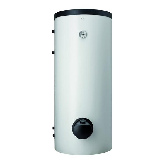
Gorenje VLG 200 A1-1G Instructions For Use Manual
Hide thumbs
Also See for VLG 200 A1-1G:
- Instructions for use manual (20 pages) ,
- Instructions for use manual (20 pages)
Advertisement
Available languages
Available languages
Quick Links
Advertisement

Subscribe to Our Youtube Channel
Summary of Contents for Gorenje VLG 200 A1-1G
- Page 1 VLG 200 - 400 INSTRUCŢIUNI DE UTILIZARE INSTRUCTIONS FOR USE www.gorenje.com...
- Page 2 AVERTISMENT Acest aparat poate fi utilizat de către copiii cu vârstă de peste 8 ani şi de către persoane cu capacităţi fizice, senzoriale sau mentale reduse sau lipsite de experienţă şi de cunoştinţe, dacă acestea au fost supravegheate sau pregătite în vederea utilizării aparatului în condiţii de siguranţă şi dacă înţeleg riscurile asociate. Copiii nu se vor juca cu aparatul.
- Page 3 Intrare apă rece 2 Scurgerea medie din schimbătorul de căldură 3 Conductă de circulaţie 4 Fluxul mediu în schimbătorul de căldură 5 Ieșire apă caldă VLG 200 A1-1G VLG 200 A3-1G VLG 300 B1-1G VLG 300 B2-1G VLG 300 C1-1G...
- Page 4 øJ LEGENDĂ Intrare apă rece 2 Scurgerea medie din schimbătorul de căldură 3 Conductă de circulaţie 4 Fluxul mediu în schimbătorul de căldură 5 Ieșire apă caldă VLG 300 C1-2G 1445 1205 G5/4 G 3/4 G5/4 Imagine 2: Măsurători de racordare și montare a boilerului [mm] øJ VLG 200 VLG 300...
- Page 5 BRANȘAREA LA ŢEVILE DE DISTRIBUIRE A APEI Pentru branșarea la reţeaua de distribuire a apei vezi indicaţiile din capitolul precedent. Pentru a se asigura o funcţionare lipsită de orice fel de riscuri, pe ţeava de intrare a apei în boiler va trebui obligatoriu să fie montat un ventil sau un grup de siguranţă, prin care se va evita creşterea presiunii din cazan cu mai mult de 0,1 MPa peste valoarea nominală.
- Page 6 BRANȘAREA LA REŢEAUA ELECTRICĂ Înainte de conectarea la reţeaua electrică este necesară instalarea în boiler a unei sfori de conectare cu secţiunea transversală minimală de cel puţin 1,5 mm (H05VV-F 3G 1,5 mm ) pentru încălzitorul de 3kW, în cazul încălzitorului de 6kW (H05VV-F 5G 2,5 mm ), de aceea trebuie să...
- Page 7 INSTALAREA SENZORILOR În partea de sus a boilerului sub capac sunt plasate două ţevi pentru senzori, unde se pot instala senzorii pentru reglarea conectării sistemului boilerului a apei calde cu alte surse de încălzire. Diametrul maxim al senzorilor este de 8 mm. Ţeavă...
- Page 8 UTILIZARE ȘI ÎNTREŢINERE După branşarea la reţeaua de distribuire a apei şi a energiei electrice, boilerul este gata de utilizare. De obicei sursa principală pentru încălzirea apei menajere este încălzirea centrală sau energia solară, iar reglarea încălzirii apei calde se efectuează în sistemul de încălzire.
- Page 9 VLG 200 A-G3 VLG 300 B-G3 VLG 400 C-G6 Puterea încălzitorului electric 3000 6000 [V ~ ] Tensiunea din reţea NE REZERVĂM DREPTUL LA MODIFICĂRI, CARE NU AFECTEAZĂ FUNCŢIONAREA APARATULUI. Instrucţiunile de utilizare sunt disponibile și pe pagina noastră de internet http://www.gorenje.com.
- Page 10 WARNINGS The appliance may be used by children aged 8 and older and persons with physical, sensory or mental disabilities or lacking experience or knowledge, if they are under supervision or taught about safe use of the appliance and if they are aware of the potential dangers. Children should not play with the appliance.
-
Page 11: Installation
Cold water inflow 2 Medium outlet from the heat exchanger 3 Circulation conduit 4 Medium inflow into the heat exchanger 5 Hot water outflow VLG 200 A1-1G VLG 200 A3-1G VLG 300 B1-1G VLG 300 B2-1G VLG 300 C1-1G VLG 400 C1-1G... - Page 12 øJ Cold water inflow 2 Medium outlet from the heat exchanger 3 Circulation conduit 4 Medium inflow into the heat exchanger 5 Hot water outflow VLG 300 C1-2G 1445 1205 G5/4 G 3/4 G5/4 Image 2: Connection and installation dimensions of the storage tank [mm] øJ VLG 200 VLG 300...
-
Page 13: Connection To The Water Supply
CONNECTION TO THE WATER SUPPLY Connection to water supply should be made according to the markings for the connections, as defined in the previous Chapter. For safety reasons the supply pipe must be fitted with a safety valve or, alternatively, a valve of the safety class that prevents the pressure in the tank from exceeding the nominal pressure by more than 0.1 MPa (1 bar). - Page 14 CONNECTION TO THE POWER SUPPLY NETWORK Before connecting the storage tank to the power supply network, a connection cable with a minimum cross-section of at least 1.5 mm (H05VV-F 3G 1.5 mm ) for a 3kW-heating element and 2.5 mm for a 6kW-heating element (H05VV-F 5G 2,5 mm ) must be installed in it and the protection cover must be removed.
-
Page 15: Installation Of Sensors
INSTALLATION OF SENSORS On the upper side of the storage tank there are two sensor tubes for mounting the sensors for regulation of the system connection of the hot water storage tank to other heating sources. The maximum diameter of the sensors is 8 mm. Long sensor tube (lower tank position) Short sensor tube (upper tank position) Image 6: Installation of sensors... -
Page 16: Use And Maintenance
USE AND MAINTENANCE The hot water storage tank is ready for use once it has been connected to water and electricity and other heating sources. The usual main sources for heating domestic water are central heating or solar power; in this case any regulation of water heating is performed in the heating system. - Page 17 VLG 200 A-G3 VLG 300 B-G3 VLG 400 C-G6 Connected load 3000 6000 [V ~ ] Voltage WE RESERVE THE RIGHT TO ANY MODIFICATIONS NOT AFFECTING THE FUNCTIONALITY OF THE APPLIANCE. The instructions for use are also available on our website http://www.gorenje.com.
- Page 20 VLG 200 - 400 05/2017 518371...


Need help?
Do you have a question about the VLG 200 A1-1G and is the answer not in the manual?
Questions and answers