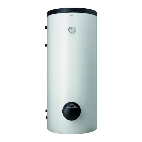
Gorenje VLG 200 A1-1G Instructions For Use Manual
Hide thumbs
Also See for VLG 200 A1-1G:
- Instructions for use manual (20 pages) ,
- Instructions for use manual (20 pages)
Advertisement
Available languages
Available languages
Quick Links
Advertisement

Summary of Contents for Gorenje VLG 200 A1-1G
- Page 1 VLG 200 - 400 UPUTE ZA UPOTREBU INSTRUCTIONS FOR USE www.gorenje.com...
- Page 2 UPOZORENJA Uređaj mogu koristiti djeca starija od 8 godina te osobe sa smanjenim fizičkim, psihičkim ili mentalnim sposobnostima ili osobe s nedostatkom iskustva, odnosno znanja ukoliko su pod nadzorom ili su obrazovani glede upotrebe uređaja na siguran način, te da razumiju moguće opasnosti. Djeca se ne smiju igrati s uređajem.
- Page 3 Dotok hladne vode 2 Izlazak medija iz prijenosnika topline 3 Cirkulacijski vod 4 Ulazak medija u prijenosnik topline 5 Otjecanje tople vode VLG 200 A1-1G VLG 200 A3-1G VLG 300 B1-1G VLG 300 B2-1G VLG 300 C1-1G VLG 400 C1-1G...
- Page 4 øJ LEGENDA Dotok hladne vode 2 Izlazak medija iz prijenosnika topline 3 Cirkulacijski vod 4 Ulazak medija u prijenosnik topline 5 Otjecanje tople vode VLG 300 C1-2G 1445 1205 G5/4 G 3/4 G5/4 Sl. 2: Priključne i montažne mjere spremnika (mm) øJ VLG 200 VLG 300...
- Page 5 PRIKLJUČENJE NA VODOVODNU MREŽU Priključenje na vodovodnu mrežu napravite prema uputama za priključenje iz prethodnog poglavlja. Na dovodnu cijev, zbog jamčenja sigurnosti kod rada spremnika potrebno je ugraditi sigurnosni ventil ili sigurnosnu grupu koja sprječava povećanje tlaka u kotlu za više od 0,1 MPa (1 bara) iznad nominalnog tlaka. Odvodni otvor na sigurnosnom ventilu obavezno mora imati izlaz na atmosferski tlak.
- Page 6 PRIKLJUČENJE NA ELEKTRIČNU MREŽU Prije priključenja u električnu mrežu potrebno je u spremnik ugraditi priključnu uzicu minimalnog presjeka barem 1,5 mm (H05VV-F 3G 1,5 mm ) za 3kW grijač, u slučaju 6kW grijača (H05VV-F 5G 2,5 mm ), zato morate skinuti zaštitni poklopac. To učinite na način da prvo izvučete gumb koji je umetnut na os termostata te odšarafite vijak.
- Page 7 NAMIJEŠTANJE SONDI Na gornjoj strani spremnika ispod pokrova postavljene su dvije cijevi za sonde gdje se mogu umetnuti sonde za regulaciju sistemske povezanosti spremnika tople vode i drugih izvora grijanja. Maksimalni promjer sondi je 8 mm. Duža cijev za sondu (donja pozicija kotla) Kraća cijev za sondu (gornja pozicija kotla) Sl.
- Page 8 UPOTREBA I ODRŽAVANJE Nakon priključenja na vodovodnu i električnu mrežu te druge izvore grijanja spremnik tople vode je spreman za upotrebu. Obično je osnovni izvor grijanja sanitarne vode centralno grijanje ili sunčeva energija, pri čemu je regulacija grijanja tople vode provedena u sistemu grijanja.
- Page 9 Testirano po SIST EN 60379:2005 Model VLG 200 A-G3 VLG 300 B-G3 VLG 400 C-G6 Potrošnja struje 3000 6000 [V ~ ] Napon PRIDRŽAVAMO PRAVA NA PROMJENE KOJE NE UTJEČU NA FUNKCIONALNOST APARATA. Upute za korištenje dostupne su na našim web stranicama http://www.gorenje.com.
- Page 10 WARNINGS The appliance may be used by children aged 8 and older and persons with physical, sensory or mental disabilities or lacking experience or knowledge, if they are under supervision or taught about safe use of the appliance and if they are aware of the potential dangers. Children should not play with the appliance.
-
Page 11: Installation
Cold water inflow 2 Medium outlet from the heat exchanger 3 Circulation conduit 4 Medium inflow into the heat exchanger 5 Hot water outflow VLG 200 A1-1G VLG 200 A3-1G VLG 300 B1-1G VLG 300 B2-1G VLG 300 C1-1G VLG 400 C1-1G... - Page 12 øJ Cold water inflow 2 Medium outlet from the heat exchanger 3 Circulation conduit 4 Medium inflow into the heat exchanger 5 Hot water outflow VLG 300 C1-2G 1445 1205 G5/4 G 3/4 G5/4 Image 2: Connection and installation dimensions of the storage tank [mm] øJ VLG 200 VLG 300...
-
Page 13: Connection To The Water Supply
CONNECTION TO THE WATER SUPPLY Connection to water supply should be made according to the markings for the connections, as defined in the previous Chapter. For safety reasons the supply pipe must be fitted with a safety valve or, alternatively, a valve of the safety class that prevents the pressure in the tank from exceeding the nominal pressure by more than 0.1 MPa (1 bar). - Page 14 CONNECTION TO THE POWER SUPPLY NETWORK Before connecting the storage tank to the power supply network, a connection cable with a minimum cross-section of at least 1.5 mm (H05VV-F 3G 1.5 mm ) for a 3kW-heating element and 2.5 mm for a 6kW-heating element (H05VV-F 5G 2,5 mm ) must be installed in it and the protection cover must be removed.
-
Page 15: Installation Of Sensors
INSTALLATION OF SENSORS On the upper side of the storage tank there are two sensor tubes for mounting the sensors for regulation of the system connection of the hot water storage tank to other heating sources. The maximum diameter of the sensors is 8 mm. Long sensor tube (lower tank position) Short sensor tube (upper tank position) Image 6: Installation of sensors... -
Page 16: Use And Maintenance
USE AND MAINTENANCE The hot water storage tank is ready for use once it has been connected to water and electricity and other heating sources. The usual main sources for heating domestic water are central heating or solar power; in this case any regulation of water heating is performed in the heating system. - Page 17 VLG 200 A-G3 VLG 300 B-G3 VLG 400 C-G6 Connected load 3000 6000 [V ~ ] Voltage WE RESERVE THE RIGHT TO ANY MODIFICATIONS NOT AFFECTING THE FUNCTIONALITY OF THE APPLIANCE. The instructions for use are also available on our website http://www.gorenje.com.
- Page 20 VLG 200 - 400 05/2017 518362...


Need help?
Do you have a question about the VLG 200 A1-1G and is the answer not in the manual?
Questions and answers