turck LTX-R10 Series Instructions For Use Manual
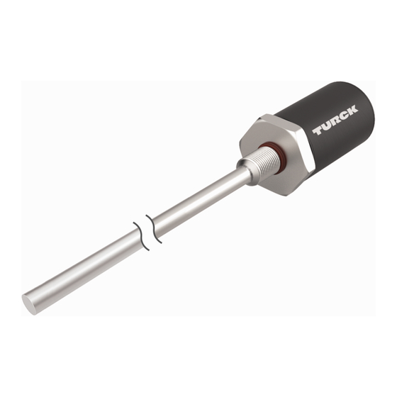
Linear position sensors with analog output
Hide thumbs
Also See for LTX-R10 Series:
- Instructions for use manual (30 pages) ,
- Manual (20 pages) ,
- Operating instructions manual (24 pages)

Related Manuals for turck LTX-R10 Series


Summary of Contents for turck LTX-R10 Series
- Page 1 Your Global Automation Partner Linear Position Sensors with Analog Output Instructions for Use...
- Page 2 Hans Turck GmbH & Co. KG | T +49 208 4952-0 | F +49 208 4952-264 | more@turck.com | www.turck.com...
-
Page 3: Table Of Contents
Other documents ...................... 5 Feedback about these instructions................ 5 Notes on the product......................... 6 Product identification..................... 6 Scope of delivery ...................... 6 Turck service........................ 6 For your safety ............................ 7 Intended use........................ 7 General safety instructions.................... 7 Product description.......................... 8 Device overview ...................... - Page 4 12 Repair.............................. 26 12.1 Returning devices...................... 26 13 Disposal .............................. 26 14 Technical data ........................... 27 14.1 Update time........................ 27 15 Turck subsidiaries – contact information.................. 28 Hans Turck GmbH & Co. KG | T +49 208 4952-0 | F +49 208 4952-264 | more@turck.com | www.turck.com...
-
Page 5: About These Instructions
This symbol denotes actions that the user must carry out. RESULTS OF ACTION This symbol denotes relevant results of actions. Other documents Besides this document, the following material can be found on the Internet at www.turck.com: Data sheet Declarations of conformity (current versions) Feedback about these instructions We make every effort to ensure that these instructions are as informative and as clear as pos- sible. -
Page 6: Notes On The Product
CAD files in numerous export formats. The contact details of Turck subsidiaries worldwide can be found on p. [} 28]. Hans Turck GmbH & Co. KG | T +49 208 4952-0 | F +49 208 4952-264 | more@turck.com | www.turck.com... -
Page 7: For Your Safety
The product is designed according to state-of-the-art technology. However, residual risks still exist. Observe the following warnings and safety notices to prevent damage to persons and property. Turck accepts no liability for damage caused by failure to observe these warning and safety notices. -
Page 8: Product Description
Degree of protection IP68 16-bit resolution Status indication via 3-color LED Sensor and pressure pipe can be replaced separately M12 connector Hans Turck GmbH & Co. KG | T +49 208 4952-0 | F +49 208 4952-264 | more@turck.com | www.turck.com... -
Page 9: Operating Principle
Operating principle The operation of the Turck LTX sensors is based on the magnetostrictive principle. A so-called “waveguide” is located in the measuring probe of the linear position sensor. If a current signal generated on the waveguide hits the magnetic field of the positioning element applied from outside, this produces a mechanical feedback in the waveguide. -
Page 10: Preferred Types Ltx
Measuring range Configured 100…500 mm in 25 mm increments 500…2000 mm in 50 mm increments 2000…7600 mm in 500 mm increments Hans Turck GmbH & Co. KG | T +49 208 4952-0 | F +49 208 4952-264 | more@turck.com | www.turck.com... -
Page 11: Technical Accessories
Technical accessories The following accessories are not supplied with the device: Positioning element Dimension drawing Type Description STM-AL-R10 6900409 Standard 4-hole positioning element, aluminum, suitable for mounting in the ø 32,8 hydraulic cylinder ø 4,7 ø 23,8 ø 13,5 16,8 CM-R10 6900416 Standard positioning element, suitable for... - Page 12 ø 4,7 hydraulic piston rod, suitable for mounting in ø 23,8 the hydraulic cylinder ø 13,5 16,8 Hans Turck GmbH & Co. KG | T +49 208 4952-0 | F +49 208 4952-264 | more@turck.com | www.turck.com...
- Page 13 Accessories for external mounting Dimension drawing Type Description MMB-R10 6900004 Mounting bracket for positioning element, for 23,8 ø 14,2 external mounting, with screws and standard #6-32 STS-R10 spacer 76,2 ø 7,1 50,8 31,7 15,7 50,8 25,4 MB-R10 6900419 Mounting bracket, sensor head and rod, for ø...
- Page 14 More information on this is available from the Turck product database at www.turck.de/products in the Connectivity area. Hans Turck GmbH & Co. KG | T +49 208 4952-0 | F +49 208 4952-264 | more@turck.com | www.turck.com...
-
Page 15: Installing
Installing The device can be mounted in a hydraulic cylinder or externally with a mounting bracket. NOTICE Incorrect mounting Risk of damage to the sensor „ Secure the device in place using only the hexagon nut on the sensor head (max. -
Page 16: Mounting The Device In A Hydraulic Cylinder
To fasten the device, an M18 × 1.5 threaded hole according to ISO 6149-1 is required in the end cap of the hydraulic cylinder. Hans Turck GmbH & Co. KG | T +49 208 4952-0 | F +49 208 4952-264 | more@turck.com | www.turck.com... -
Page 17: Mounting The Sensor
5.1.1 Mounting the sensor „ Loosen the hexagon nut on the sensor and remove from the thread. „ Ensure that the pressure seal O-ring is located on the sensor head. „ Mount the non-ferrous spacer between the positioning element and base of the piston rod. -
Page 18: Fastening The Device With Mounting Bracket Externally
11 [0.43] 32 [1.26] 25.4 [1.00] ø 7.1 [0.28] 50.8 [2.00] 50.8 [2.00] Fig. 8: Mounting a device with mounting brackets Hans Turck GmbH & Co. KG | T +49 208 4952-0 | F +49 208 4952-264 | more@turck.com | www.turck.com... -
Page 19: Mounting Additional Mounting Brackets (For External Mounting)
5.2.1 Mounting additional mounting brackets (for external mounting) On devices over 750 mm in length, additional mounting elements (RB-R10) increase protection against mechanical stresses such as impacts and vibrations. The mounting elements must be made from non-ferrous material. „ When using additional mounting elements, use a ring-type positioning element with slot as the positioning element. -
Page 20: Installing The Positioning Element (For External Mounting)
Mounting element for sensor head 4-hole positioning element (aluminum) Spacer for positioning element Mounting element for positioning element Mounting element for measuring probe Hans Turck GmbH & Co. KG | T +49 208 4952-0 | F +49 208 4952-264 | more@turck.com | www.turck.com... -
Page 21: Connection
Connection NOTICE Couplings on the sensor cable Sensor fault „ Do not route the sensor cable close to high voltage power supplies. „ Keep the length of the connection lines as short as possible. „ Use shielded connection cables. „ Keep the sensor cables away from high-power AC cables and motor drive cables. -
Page 22: Commissioning
The positioning element must be located in the active measuring range of the sensor when the power supply is applied in order to ensure the correct tuning of the signal strength control. Hans Turck GmbH & Co. KG | T +49 208 4952-0 | F +49 208 4952-264 | more@turck.com | www.turck.com... -
Page 23: Operation
Operation LED indication Color Meaning No power supply present Green Positioning element signal detected within taught range Yellow Positioning element signal detected outside taught range No positioning element signal detected Proceed as follows if no magnetic signal is detected (red LED lit): „... -
Page 24: Setting
Press the Span button of the teach adapter again within 5 s. The end point of the measuring range is stored. Hans Turck GmbH & Co. KG | T +49 208 4952-0 | F +49 208 4952-264 | more@turck.com | www.turck.com... -
Page 25: Troubleshooting
Troubleshooting If the device does not operate as expected, check the LED feedback signal (see the section “LED indication”) Check whether any ambient interference is present. If there is no ambient interfer- ence present, check the connections of the device for faults. If there are no faults, there is a device malfunction. -
Page 26: Maintenance
Disposal The devices must be disposed of correctly and must not be included in general household garbage. Hans Turck GmbH & Co. KG | T +49 208 4952-0 | F +49 208 4952-264 | more@turck.com | www.turck.com... -
Page 27: Technical Data
Technical data Technical data LTX-R10…/LTX-F10… LTX-ER10…/LTX-EF10… Measuring range specifications Blind zone (connector end) 50.8 mm Blind zone (end) 63.5 mm Repetition accuracy ≤ 0.01 % of full scale Resolution 16 bit Linearity ≤ 0.01 % of full scale Operating temperature, rod -40…+105 °C Operating temperature, -40…+85 °C... -
Page 28: Turck Subsidiaries - Contact Information
Turck Banner Malaysia Sdn Bhd Unit A-23A-08, Tower A, Pinnacle Petaling Jaya, Jalan Utara C, 46200 Petaling Jaya Selangor www.turckbanner.my Hans Turck GmbH & Co. KG | T +49 208 4952-0 | F +49 208 4952-264 | more@turck.com | www.turck.com... - Page 29 Mexico Turck Comercial, S. de RL de CV Blvd. Campestre No. 100, Parque Industrial SERVER, C.P. 25350 Arteaga, Coahuila www.turck.com.mx Netherlands Turck B. V. Ruiterlaan 7, NL-8019 BN Zwolle www.turck.nl Austria Turck GmbH Graumanngasse 7/A5-1, A-1150 Wien www.turck.at Poland TURCK sp.z.o.o.
- Page 30 Over 30 subsidiaries and over 60 representations worldwide! D102240 | 2022/04 D102240 www.turck.com...
Need help?
Do you have a question about the LTX-R10 Series and is the answer not in the manual?
Questions and answers