
Related Manuals for turck RU40U/3GD Series


Summary of Contents for turck RU40U/3GD Series
- Page 1 Your Global Automation Partner RU…/3GD High End Ultrasonic sensors with ex approval Operating instructions...
- Page 2 Table of contents Hans Turck GmbH & Co. KG | T +49 (0)208 4952-0 | F +49 (0)208 4952-264 | more@turck.com | www.turck.com...
-
Page 3: Table Of Contents
Table of contents About these instructions Target groups Explanation of symbols Additional documents Feedback on these instructions Notes on the product Product identification Scope of delivery Legal requirements Manufacturer and service For your safety Intended use Obvious misuse General safety instructions Explosion protection notes 3.4.1 Special conditions for use in zone 2 (requirements of the test body) - Page 4 Special conditions for use in zone 2 (requirements of the test body) 15.3 Approvals: cULus 15.4 Certificates of conformity 15.5 Approvals 15.5.1 EX type-examination certificate 15.5.2 IECEx certificate of conformity Hans Turck GmbH & Co. KG | T +49 (0)208 4952-0 | F +49 (0)208 4952-264 | more@turck.com | www.turck.com...
-
Page 5: About These Instructions
This symbol identifies steps that the user has to perform. ACTION RESULT ➥ This symbol identifies relevant results of actions and action sequences. Additional documents You will find the following supplementary documents online at www.turck.com: ■ Data sheet ■ Quick start guide ■... -
Page 6: Feedback On These Instructions
Should you have any suggestions for a better design or any information is missing from the instructions, please send your suggestions to techdoc@turck.com. Hans Turck GmbH & Co. KG | T +49 (0)208 4952-0 | F +49 (0)208 4952-264 | more@turck.com | www.turck.com... -
Page 7: Notes On The Product
Notes on the product Product identification RU 300 U – EM30 E LIU2 PN 8 X2 T – H1 1 5 1 – Electrical RU 300 U – EM30 E – LIU2 PN 8 X2 T – Series Design version Series Housing length with teach... -
Page 8: Manufacturer And Service
Outside Germany, please contact your Tûrck representative. Hans Turck GmbH & Co. KG Witzlebenstraße 7 45472 Mülheim an der Ruhr Germany Hans Turck GmbH & Co. KG | T +49 (0)208 4952-0 | F +49 (0)208 4952-264 | more@turck.com | www.turck.com... -
Page 9: For Your Safety
The product is designed according to the state of the art. However, residual risks still exist. Ob- serve the following warnings and safety regulations to prevent danger to persons and property. Turck accepts no liability for damage caused by failure to observe these warning and safety instructions. -
Page 10: Explosion Protection Notes
Connect the device using a separately-certified M12 plug connection. The plug connection must meet the requirements of IEC/EN 61076-2-101. ■ Ensure external grounding by assembly. Hans Turck GmbH & Co. KG | T +49 (0)208 4952-0 | F +49 (0)208 4952-264 | more@turck.com | www.turck.com... -
Page 11: Product Description
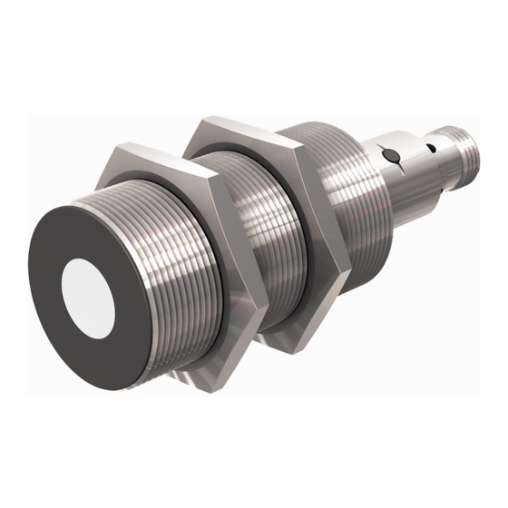
Product description The devices have a metal housing with an M18 or M30 male thread. The sonic transducer sur- face can be mounted flush to the surrounding area. All devices are connected to the sensor cable via an M12 male connector in metal. To detect the object, it is possible to configure a switching distance that is less than or equal to the maximum sensing range and that must be greater than the minimum switching distance. -
Page 12: Functional Principle
Users can set a single switching point or a window or hysteresis function. Additional operating modes (throughbeam, multiplex, synchronous or release mode) can be parameter- ized via IO-Link. Hans Turck GmbH & Co. KG | T +49 (0)208 4952-0 | F +49 (0)208 4952-264 | more@turck.com | www.turck.com... -
Page 13: Setting Options
4.4.1 Setting options The devices have three setting options: ■ Setting via manual bridging (short-circuit) ■ Setting via connected teach adapter (accessories to be ordered separately) ■ Setting via buttons 4.4.2 Diffuse mode sensors When using diffuse mode sensors, either a switching point or a switching window is defined. The switching window is used for window or hysteresis functions. - Page 14 Fig. 7: Hysteresis function — behavior of the switching output Hans Turck GmbH & Co. KG | T +49 (0)208 4952-0 | F +49 (0)208 4952-264 | more@turck.com | www.turck.com...
-
Page 15: Retro-Reflective Mode Sensors
Behavior of the analog output Output 2 is factory set as an analog output and can be used either as a 4…20 mA/0…20 mA current output, a 0…10 V/0…5 V/1…6 V voltage output or as a switching output. The analog output behaves as follows: [mA] blind [mA] blind... - Page 16 In throughbeam mode, all connected sensors must have the same power and range. In throughbeam mode, connect only sensors with the same type code. The type code is printed on every device. Hans Turck GmbH & Co. KG | T +49 (0)208 4952-0 | F +49 (0)208 4952-264 | more@turck.com | www.turck.com...
-
Page 17: Technical Accessories
Technical accessories The following accessories are not included in the scope of delivery: Article name Description Figure TX1-Q20L60 Teach adapter M12 x 1 ø 4.5 USB 2-IOL-0002 IO-Link adapter V1.1 with inte- grated USB interface LED: USB-Mini CH1 (C/Q) LED: PWR CH2 (DI/DO) IN-DC Error... - Page 18 "High-End" ultrasonic sensor. Further information can be found in the Connectivity section of the Turck product database at http://pdb2.turck.de/en/DE/groups/ Hans Turck GmbH & Co. KG | T +49 (0)208 4952-0 | F +49 (0)208 4952-264 | more@turck.com | www.turck.com...
-
Page 19: Mounting
Mounting DANGER Explosive atmospheres Explosion due to ignitable sparks Use of devices in Zone 2 and Zone 22 Only mount the device if there is no potentially explosive atmosphere present. ➤ ➤ Protect the device’s connector against accidental removal during operation using ➤... -
Page 20: Connection
… n ≤ 9 Out 1 Out 2 Slave n Out 2 Master 5 n.c. Fig. 16: Wiring diagram for multiplex mode Hans Turck GmbH & Co. KG | T +49 (0)208 4952-0 | F +49 (0)208 4952-264 | more@turck.com | www.turck.com... - Page 21 Connection diagram of the master sensor in multiplex mode Pin assignment Connection image Pin 1 + 24 VDC 2 WH Pin 2 Output 2 (analog output or switching output) 3 BU 1 BN Pin 3 5 GY 4 BK Pin 4 Multiplex output, connected to pin 5 on the slaves Pin 5...
-
Page 22: Connection - Synchronization Mode
Synchronization input, connected to pin 4 on the master sensor Fig. 21: Connection diagram of the master sensor in synchronization mode Hans Turck GmbH & Co. KG | T +49 (0)208 4952-0 | F +49 (0)208 4952-264 | more@turck.com | www.turck.com... -
Page 23: Connection - Release Mode
Connection — release mode Connection diagram of the master sensor in release mode Pin assignment Connection image Pin 1 +24 VDC 2 WH Pin 2 Output 2 (analog output or switching output) 3 BU 1 BN Pin 3 5 GY 4 BK Pin 4 Output 1 (switching output) -
Page 24: Commissioning
Object between sensor and reflector, switching output 1 off No object within the sensing range, switching output 1 off Switching output 2 behaves inverted to switching output 1. Hans Turck GmbH & Co. KG | T +49 (0)208 4952-0 | F +49 (0)208 4952-264 | more@turck.com | www.turck.com... -
Page 25: Operating In Io-Link Mode - Led Displays
Operating in IO-Link mode — LED displays In IO-Link mode, the LEDs have the following output function: LED display Meaning Green, lights IO-Link mode started up with short interruptions Setting DANGER Explosive atmospheres Explosion due to ignitable sparks Parameterize the device only if the atmosphere is not explosive. ➤... -
Page 26: Setting
5 Hz U B / T2 > 2 s Canceled 1.5 s Cancel Fig. 26: Overview of the teach-in process Hans Turck GmbH & Co. KG | T +49 (0)208 4952-0 | F +49 (0)208 4952-264 | more@turck.com | www.turck.com... -
Page 27: Set Via Teach Adapter
Set via teach adapter Select output Select switching output 1: Press and hold down the pushbutton on the adapter to GND for ➤ ➤ 2…7 s. Select output 2: Press and hold down the pushbutton on the adapter to GND for 8…13 s. ➤... - Page 28 Output 2 is set successfully as a switching output if the green LED flashes for 1.5 s at a fre- ➥ ➤ quency of 5 Hz. Hans Turck GmbH & Co. KG | T +49 (0)208 4952-0 | F +49 (0)208 4952-264 | more@turck.com | www.turck.com...
-
Page 29: Setting Via Manual Bridging (Short-Circuit)
Setting via manual bridging (short-circuit) Select output Select switching output 1: Bridge pin 3 (BU) with pin 5 (GY) for 2...7 s. ➤ ➤ Select output 2: Bridge pin 3 (BU) with pin 5 (GY) for 8...13 s. ➤ ➤ Set the switching point Select the switching output. - Page 30 Output 2 is set successfully as a switching output if the green LED flashes for 1.5 s at a fre- ➥ ➤ quency of 5 Hz. Hans Turck GmbH & Co. KG | T +49 (0)208 4952-0 | F +49 (0)208 4952-264 | more@turck.com | www.turck.com...
-
Page 31: Settings Made Via Buttons
Settings made via buttons NOTE The devices with a teach pushbutton are ready for teaching up to 300 s after the power supply is switched on. The teach pushbutton is then automatically locked. A new teach operation is only possible after the power supply has been reset. Select output Select switching output 1: Press and hold down pushbutton 1 for 2...7 s. -
Page 32: Setting Via Io-Link
If there are no faults, there is a device malfunction. In this case, decommission the device and replace it with a new device of the same type. Hans Turck GmbH & Co. KG | T +49 (0)208 4952-0 | F +49 (0)208 4952-264 | more@turck.com | www.turck.com... -
Page 33: Maintenance
Repairs The device is not intended for repair by the user. If the device is faulty, please take it out of op- eration. If you are returning the device to Turck, please note our return terms and conditions. 12.1 Returning devices If a device has to be returned, bear in mind that only devices with a decontamination declara- tion will be accepted. -
Page 34: Technical Data
4 Hz 1.6 Hz Approvals CE, cULus CE, cULus UL conditions: T 0…+85°C, use the same supply for all circuits. Hans Turck GmbH & Co. KG | T +49 (0)208 4952-0 | F +49 (0)208 4952-264 | more@turck.com | www.turck.com... -
Page 35: Appendix: Declarations Of Conformity And Approvals
Appendix: Declarations of conformity and approvals 15.1 Approvals and labels Approvals Marking parts in accordance with ATEX directive EN 60079-0 resp. 15 or 31 ATEX Devices with teach button: Devices with teach button: ÉII 3 G Certificate number: Ex nA nC IIC T6 Gc BVS16 ATEX E021 X ÉII 3 D Ex tc IIIC T70°C Dc... -
Page 36: Certificates Of Conformity
Appendix: Declarations of conformity and approvals 15.4 Certificates of conformity Hans Turck GmbH & Co. KG | T +49 (0)208 4952-0 | F +49 (0)208 4952-264 | more@turck.com | www.turck.com... -
Page 37: Approvals
15.5 Approvals 15.5.1 EX type-examination certificate V01.01 | 2016/10... - Page 38 Appendix: Declarations of conformity and approvals Hans Turck GmbH & Co. KG | T +49 (0)208 4952-0 | F +49 (0)208 4952-264 | more@turck.com | www.turck.com...
- Page 39 V01.01 | 2016/10...
-
Page 40: Iecex Certificate Of Conformity
3. The Status and authenticity of this certificate may be verified by visiting the Official IECEx Website. Certificate issued by: DEKRA EXAM GmbH Dinnendahlstrasse 9 44809 Bochum Germany Hans Turck GmbH & Co. KG | T +49 (0)208 4952-0 | F +49 (0)208 4952-264 | more@turck.com | www.turck.com... - Page 41 IECEx BVS 16.0035X Issue No: 0 Page 2 of 4 Date of Issue: 2016-05-31 Manufacturer: Werner Turck GmbH & Co. KG Goethestr. 7 58545 Halver Germany Additional Manufacturing location(s): This certificate is issued as verification that a sample(s), representative of production, was assessed and tested and found to comply with the IEC Standard list below and that the manufacturer's quality system, relating to the Ex products covered by this certificate, was assessed and found to comply with the IECEx Quality system requirements.
- Page 42 The connector has to comply with the requirements according EN/IEC 61076-2-101. The external earthing has to be established by the end user in the end use application. Hans Turck GmbH & Co. KG | T +49 (0)208 4952-0 | F +49 (0)208 4952-264 | more@turck.com | www.turck.com...
- Page 43 IECEx Certificate of Conformity Certificate No: IECEx BVS 16.0035X Issue No: 0 Page 4 of 4 Date of Issue: 2016-05-31 EQUIPMENT (continued): Parameters Electrical data Nominal voltage 15...30 VDC Nominal current ≤150 mA Ultrasonic frequency 80 up to 300 kHz Thermal data Ambient temperature range -25 °C ≤...
- Page 44 Page 1 of 1 Subject and Type Ultrasonic sensor type RU***-M***-***8X2*-H1151/S****/3GD Category Special version Electrical parameters Size of the enclosure Range in cm Hans Turck GmbH & Co. KG | T +49 (0)208 4952-0 | F +49 (0)208 4952-264 | more@turck.com | www.turck.com...
- Page 45 V01.01 | 2016/10...
- Page 46 ...with 28 subsidiaries and over 60 representations worldwide! D102265 | 2016/10 *D102265ßß1610* www.turck.com...
Need help?
Do you have a question about the RU40U/3GD Series and is the answer not in the manual?
Questions and answers