turck LTX Series Operating Instructions Manual
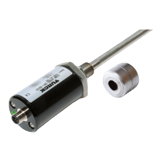
Linear position sensors with analog output
Hide thumbs
Also See for LTX Series:
- Operating instructions manual (22 pages) ,
- Operating instructions manual (24 pages)

Related Manuals for turck LTX Series


Summary of Contents for turck LTX Series
- Page 1 Your Global Automation Partner Linear Position Sensors with Analog Output Operating instructions...
- Page 2 Contents Hans Turck GmbH & Co. KG | T +49 208 4952-0 | F +49 208 4952-264 | more@turck.com | www.turck.com...
-
Page 3: Table Of Contents
Contents About These Instructions Target groups Explanation of symbols Other documents Feedback about these instructions Information About the Product Product identification Scope of delivery Legal requirements Manufacturer and service For your Safety Intended use General safety information Product Description Device overview 4.1.1 Display elements Properties and features... - Page 4 Maintenance Repair 12.1 Returning devices Disposal Technical Data 14.1 Update time Hans Turck GmbH & Co. KG | T +49 208 4952-0 | F +49 208 4952-264 | more@turck.com | www.turck.com...
-
Page 5: About These Instructions
We make every effort to ensure that these instructions are as informative and as clear as pos- sible. If you have any suggestions for improving the design or if any information is missing from the instructions, please send your suggestions to techdoc@turck.com. 2019/03... -
Page 6: Information About The Product
Linear position sensor (without positioning element) ■ Quick Start Guide Legal requirements The device is subject to the following EU directives: ■ 2014/30/EU (electromagnetic compatibility) Hans Turck GmbH & Co. KG | T +49 208 4952-0 | F +49 208 4952-264 | more@turck.com | www.turck.com... -
Page 7: Manufacturer And Service
Manufacturer and service Turck provides you with support and assistance for your projects — from the initial analysis to commissioning your application. The Turck product database contains software tools for pro- gramming, configuration and commissioning, as well as data sheets and CAD files in numerous export formats. -
Page 8: Product Description
16-bit resolution ■ Status display via 3-color LED ■ Sensor and pressure pipe can be replaced separately ■ M12 connector Hans Turck GmbH & Co. KG | T +49 208 4952-0 | F +49 208 4952-264 | more@turck.com | www.turck.com... -
Page 9: Operating Principle
Operating principle Turck LTX sensors utilize the magnetostrictive principle. A "waveguide" is located in the measur- ing probe of the linear position sensor. If a current signal generated at the waveguide encoun- ters the externally applied magnetic field of the positioning element, mechanical feedback is produced in the waveguide. -
Page 10: Technical Accessories
ø 23,8 piston rod, suitable for installation in hydrau- ø 13,5 lic cylinders 16,8 Hans Turck GmbH & Co. KG | T +49 208 4952-0 | F +49 208 4952-264 | more@turck.com | www.turck.com... - Page 11 Dimension drawing Type Ident no. Description Accessories for external mounting MMB-R10 6900004 Mounting clamp for positioning element, for 23,8 ø 14,2 external mounting, with screws and standard #6-32 STS-R10 spacer 76,2 ø 7,1 50,8 31,7 15,7 50,8 25,4 MB-R10 6900419 Mounting clamp for sensor head and rod, for ø...
- Page 12 Further information can be found in the Connectivity section of the Turck product database at https://pdb2.turck.de/en/DE/groups/. Hans Turck GmbH & Co. KG | T +49 208 4952-0 | F +49 208 4952-264 | more@turck.com | www.turck.com...
-
Page 13: Mounting
Mounting The device can be mounted in a hydraulic cylinder or externally with a mounting bracket. CAUTION Incorrect mounting Risk of damage to the sensor Secure the device in place using only the hexagon nut on the sensor head (max. ➤... -
Page 14: Mounting The Device In A Hydraulic Cylinder
Spacer for positioning element 13.5 mm bore hole in the cylinder piston rod Fig. 7: Mounting the device in a hydraulic cylinder Hans Turck GmbH & Co. KG | T +49 208 4952-0 | F +49 208 4952-264 | more@turck.com | www.turck.com... -
Page 15: Fastening The Device Externally With A Mounting Bracket
Fastening the device externally with a mounting bracket CAUTION Magnetization of metal in close proximity with the measuring probe Inaccurate measurements Mount the sensor measuring probe at least 7 mm away from ferromagnetic material. ➤ ➤ NOTE Non-ferrous materials, such as brass, copper, aluminum, demagnetized stainless steel or plastic do not impair the function of the sensor. -
Page 16: Fitting Additional Mounting Elements (For External Mounting)
Mounting element for measuring probe 50.8 15.7 25.4 31.8 ø 7.1 (2x) 50.8 Fig. 9: Mounting the positioning element (dimensions in mm) Hans Turck GmbH & Co. KG | T +49 208 4952-0 | F +49 208 4952-264 | more@turck.com | www.turck.com... -
Page 17: Connection
Connection CAUTION Couplings on the sensor cable Sensor fault Do not route sensor cables close to high-voltage power supplies. ➤ ➤ NOTE Keep the length of the connection cables as short as possible. ➤ ➤ Use shielded connection cables. ➤ ➤... -
Page 18: Commissioning
3.8 mA: Positioning element is located in the blind zone or no positioning element detected ■ 3.9 mA or 20.1 mA: Positioning element is located outside of the set measuring range Hans Turck GmbH & Co. KG | T +49 208 4952-0 | F +49 208 4952-264 | more@turck.com | www.turck.com... -
Page 19: Led Display
Setting The devices have an adjustable analog output. The measuring range can be set by manual bridging or with the RP-Q21 teach adapter. The zero point and end point of the measuring range can be set in succession or independently of one another. Setting via manual bridging Supply the device with voltage. -
Page 20: Replacing The Sensor Head And Measuring Element
Ensure that the plug connections and connection cables are always in good condition. The devices are maintenance-free; clean using dry materials as required. Hans Turck GmbH & Co. KG | T +49 208 4952-0 | F +49 208 4952-264 | more@turck.com | www.turck.com... -
Page 21: Repair
Repair The device must not be repaired by the user. Take detective devices out of operation. Observe our return acceptance conditions when returning the device to Turck. 12.1 Returning devices If a device has to be returned, please be aware that only devices with a decontamination decla- ration will be accepted. -
Page 22: Technical Data
750 mm 2 ms 1250 mm 3 ms 2500 mm 4 ms 3800 mm 5 ms 4550 mm 6 ms 6350 mm 7 ms 7600 mm 8 ms Hans Turck GmbH & Co. KG | T +49 208 4952-0 | F +49 208 4952-264 | more@turck.com | www.turck.com... - Page 23 2019/03...
- Page 24 Over 30 subsidiaries and over 60 representations worldwide! D102240 | 2019/03 *D102240* www.turck.com...
Need help?
Do you have a question about the LTX Series and is the answer not in the manual?
Questions and answers