turck LTX Series Operating Instructions Manual
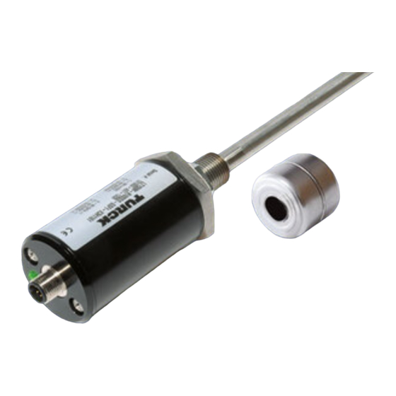
Linear position sensors with ssi interface
Hide thumbs
Also See for LTX Series:
- Operating instructions manual (24 pages) ,
- Operating instructions manual (24 pages)

Related Manuals for turck LTX Series


Summary of Contents for turck LTX Series
- Page 1 Your Global Automation Partner Linear Position Sensors with SSI Interface Operating instructions...
- Page 2 Contents Hans Turck GmbH & Co. KG | T +49 208 4952-0 | F +49 208 4952-264 | more@turck.com | www.turck.com...
-
Page 3: Table Of Contents
Contents About these Instructions Target Groups Explanation of Symbols Other Documents Feedback on these Instructions Notes on the Product Product Identification Scope of Delivery Legal Requirements Manufacturer and Service For Your Safety Intended Use General Safety Instructions Product Description Device Overview 4.1.1 Display Elements Properties and Characteristics... - Page 4 Hans Turck GmbH & Co. KG | T +49 208 4952-0 | F +49 208 4952-264 | more@turck.com | www.turck.com...
-
Page 5: About These Instructions
ACTION RESULT ➥ This symbol identifies relevant results of actions and action sequences. Other Documents Besides this document, the following material can be found on the internet at www.turck.com: ■ Data sheet Feedback on these Instructions We are committed to always keeping these instructions as informative and as clear as possible. -
Page 6: Notes On The Product
Scope of Delivery Included in the scope of delivery: ■ Linear position sensor (without positioning element) ■ Quick start guide Hans Turck GmbH & Co. KG | T +49 208 4952-0 | F +49 208 4952-264 | more@turck.com | www.turck.com... -
Page 7: Legal Requirements
2011/65/EU (RoHS 2) Manufacturer and Service Turck supports you with your projects, from initial analysis to the commissioning of your ap- plication. The Turck product database contains software tools for programming, configuration or commissioning, data sheets and CAD files in numerous export formats. You can access the product database at the following address: http://www.turck.de/products/... -
Page 8: Product Description
Display Elements Each device has a 3-color LED for indicating the operating state and for fault diagnostics (see 8.1 LED display). Hans Turck GmbH & Co. KG | T +49 208 4952-0 | F +49 208 4952-264 | more@turck.com | www.turck.com... -
Page 9: Properties And Characteristics
Male connector M12 Functional Principle Operation of the Turck LTX sensors is based on the magnetostrictive principle. A “waveguide” is located in the measuring probe of the linear position sensor. If a current signal generated at the waveguide encounters the externally applied magnetic field of the positioning element, mechanical feedback is produced in the waveguide. -
Page 10: Automatic Signal Control
Position Position Position Position Internal Repetition Update Update Update Asynchronous Position Position Position Fig. 4: Synchronous and asynchronous update mode Hans Turck GmbH & Co. KG | T +49 208 4952-0 | F +49 208 4952-264 | more@turck.com | www.turck.com... -
Page 11: Measuring Functions
Synchronous update mode The clock pulse rate of the controller sets the frequency for reading the position data. The sen- sor transmits one position data bit to the controller with each pulse. The first clock edge of the controller signals the sensor to carry out a new position measurement. The updated position data is transferred in the next read cycle. -
Page 12: Technical Accessories
ø 23,8 piston rod, suitable for installation in hydrau- ø 13,5 lic cylinders 16,8 Hans Turck GmbH & Co. KG | T +49 208 4952-0 | F +49 208 4952-264 | more@turck.com | www.turck.com... - Page 13 Dimension drawing Type Ident. no. Description Accessories for external mounting MMB-R10 6900004 Mounting clamp for positioning element, for 23,8 ø 14,2 external mounting, with screws and standard #6-32 STS-R10 spacer 76,2 ø 7,1 50,8 31,7 15,7 50,8 25,4 MB-R10 6900419 Mounting clamp for sensor head and rod, for ø...
-
Page 14: Mounting
7.1 [.28] ø 25.4 [1.00] Fig. 7: Design with raised face (R10) – Housing nut with thread, dimensions in mm [in] Hans Turck GmbH & Co. KG | T +49 208 4952-0 | F +49 208 4952-264 | more@turck.com | www.turck.com... -
Page 15: Mounting The Device In A Hydraulic Cylinder
Mounting the Device in a Hydraulic Cylinder CAUTION Incorrect mounting Risk of damage to the hydraulic cylinder Observe cylinder manufacturer instructions and hydraulic cylinder specifications. ➤ ➤ The devices can be mounted directly in a hydraulic cylinder. To do so, the cylinder piston rod must have a bore hole with a recommended diameter of 13.5 mm (depending on the cylinder design). -
Page 16: Fastening The Device Externally With Mounting Bracket
7 x 26 MMB-R10 MB-R10 25.4 ø 7.1 50.8 50.8 Fig. 9: Mounting device with mounting brackets (dimensions in mm) Hans Turck GmbH & Co. KG | T +49 208 4952-0 | F +49 208 4952-264 | more@turck.com | www.turck.com... -
Page 17: Mounting Additional Mounting Elements (For External Mounting)
5.2.1 Mounting Additional Mounting Elements (for External Mounting) On devices over 750 mm in length, additional mounting elements (RB-R10) increase protection against mechanical stresses such as impacts and vibrations. The mounting elements must be made from non-ferrite material. When using additional mounting elements, use a ring-type positioning element with slot as ➤... -
Page 18: Connection
To ensure the correct calibration of the automatic signal control, the positioning ele- ment must be located in the active measuring range of the sensor when the supply voltage is connected. Hans Turck GmbH & Co. KG | T +49 208 4952-0 | F +49 208 4952-264 | more@turck.com | www.turck.com... -
Page 19: Operation
Operation LED Display Color/status Meaning No power supply present Illuminated in green Positioning element signal detected in taught range, SSI clock signal operational Illuminated in yellow No SSI clock signal detected Illuminated in red No positioning element signal detected Red flashing/red-green Internal error flashing Green with brief yellow... -
Page 20: Eliminating Interference
Disposal Devices must be properly disposed of and must not be included in general household waste. Hans Turck GmbH & Co. KG | T +49 208 4952-0 | F +49 208 4952-264 | more@turck.com | www.turck.com... -
Page 21: Technical Data
Technical Data Technical Data LTX-R10…/LTX-F10… LTX-ER10…/LTX-EF10… Measuring range specifications Blind zone (connector end) 50.8 mm Blind zone (end) 63.5 mm Resolution selectable, see type code Linearity ≤ 0.01% full scale Operating temperature, rod -40 °C … +105 °C Operating temperature, electronics -40 °C … +85 °C Temperature drift ≤... - Page 22 Over 30 subsidiaries and over 60 representations worldwide! D101914 | 2017/09 *D101914* www.turck.com...
Need help?
Do you have a question about the LTX Series and is the answer not in the manual?
Questions and answers