Table of Contents
Advertisement
Advertisement
Table of Contents

Related Manuals for Postek C168


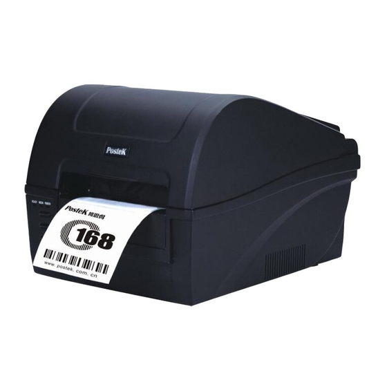
Summary of Contents for Postek C168
-
Page 2: Fcc Notice
© 2006-2009 by Postek Electronics Co., Ltd. All rights reserved. Under the copyright laws, this manual cannot be reproduced in any form without the prior written permission of Postek. No patent liability is assumed, with respect to the use of the information contained herein. - Page 3 Disclaimer This manual has been validated and reviewed for accuracy. The instructions and descriptions it contains are accurate for the Postek C168 Label Printer at the time of this manual’s printing. However, succeeding printers and manuals are subject to change without notice. Postek assumes no liability for damages incurred directly or indirectly from errors, omissions or discrepancies between the printer and this manual.
-
Page 4: Important Safety Instructions
Important Safety Instructions Only qualified and trained service technicians should attempt to repair the printer. ◆ Do not place the printer on or near a heat source. ◆ Be sure that the output of the power adapter is 24VDC and your power source ◆... -
Page 5: Table Of Contents
Contents Preface ..................1 Important Notice, Read Me First! .......... 2 Chapter 1 Introduction ............3 Specifications ................... 3 Specifications for Printer............3 Specifications for Power Adapter ..........4 Unpacking and Inspection ..............4 Chapter 2 Getting Started ............7 ... - Page 6 Chapter 4 Troubleshooting ........... 37 Error Indications ................37 Miscellaneous ................38 Others ..................... 39 Appendix A: Interface Specifications ........40 Appendix B: ASCII Table ............. 43 ...
-
Page 7: Preface
Preface Welcome to POSTEK’s C168 label printer. This manual explains how to set up and begin using your C168 printer. It also provides detailed information on configuring your printer, basic operations, care and troubleshooting. Please read this manual carefully before using the C168 printer. -
Page 8: Important Notice, Read Me First
Important Notice, Read Me First! Thermal printhead can be easily damaged due to its precision construction. A printhead damaged by misuse is not covered under the terms of the warranty. To ensure longevity of the printhead, please note the following: 1. -
Page 9: Chapter 1 Introduction
Chapter 1 Introduction Specifications Specifications for Printer Model C168/200s C168/300s Printing method Direct thermal & Thermal transfer Printing resolution 203 dpi (8 dots/mm) 300 dpi (11.8 dots/mm) Max printing speed 4 ips /s (101.6 mm) 3 ips (76.2 mm/s) Max printing width 4.09″(104 mm) -
Page 10: Specifications For Power Adapter
Storage environment Relative humidity: 5% - 85% non condensing Optional items Cutter kit, Peeler kit, Internal 100/10 M Ethernet Interface card * Power for the C168 barcode label printer is provided via an external power adaptor. Specifications for Power Adapter Input... - Page 11 Packing List(Figure 1): 1. Printer 1 pcs 2. Power Adapter 1 pcs 3. Ribbon Spindle 2 pcs 4. Media Spindle 1 pcs 5. Core Adapter 2 pcs 6. Media Roll Guide 2 pcs 7. Ribbon 1 pcs 8. Sample Media 1 pcs 9.
- Page 12 Power Adapter Printer Ribbon Spindle Ribbon Sample Media Media Spindle Core Adapter Media Roll Guide User’s Manual CD-Rom Figure 1 Printer and accessories...
-
Page 13: Chapter 2 Getting Started
Chapter 2 Getting Started Setting up Before setting up the printer you should consider the following: 1. Make sure there is adequate space around the printer for loading consumables and proper ventilation. 2. Make sure the printer is close to the host so the interface cable is easily accessible at either end. -
Page 14: Main Parts And Features
Main Parts and Features Figure 2 1. READY Indicator 2. MEDIA Indicator 3. RIBBON Indicator 4. PAUSE Button 5. FEED Button 6. CANCEL Button 7. Media Exit 8. Cover Handle 9. Top Cover... - Page 15 Figure 3 1. Printhead Module 2. Printhead Bracket 3. Printhead 4. Media Sensor 5. Platen Roller 6. TPH Release Lever 7. Media Guide 8. Ribbon Loading Knob 9. Ribbon Supply Spindle 10. Media Compartment 11.Guide Wheel...
- Page 16 5. DC IN Port 6. Power Switch 7. Centronics Port Note: The above figure illustrates all possible interface ports on a C168 printer, but some ports may not be available for your printer. Please check your requirements when purchasing the printer.
-
Page 17: Connecting The Printer
Power Connection Caution:(1) Use of the wrong adapter could damage your printer. Postek assumes no liability for any damage in such case. The rating for the printer is 24VDC. (2) Do not use the printer near liquids or corrosive chemicals. - Page 18 (Centronics) interfaces are shown in Appendix A of this guide. 4. Please take the following measures to reduce cable noise. (1)Reduce the length of the interface cable (keep the cable length under 1.83 meters / 6 feet) if required. (2)Keep the communication cable separate from power cords.
-
Page 19: Loading The Ribbon
Loading the Ribbon Caution: (1) Make sure the ink side of your ribbon faces outwards. Always make sure the ink side of the ribbon faces the media and NOT the printhead. (2) The maximum width of the ribbon is 110mm. When using a ribbon roll with a width less than 110m, please place the ribbon roll in the middle of the Ribbon Spindle corresponding to the symmetry... - Page 20 Figure 5-1...
- Page 21 Figure 5-2...
- Page 22 Figure 5-3...
- Page 23 Figure 5-4...
- Page 24 Figure 5-5...
- Page 25 Figure 5-6...
-
Page 26: Loading The Media
Loading the Media C168 printers can be operated in three different modes: Standard mode, Peel-off mode, or Cutting mode. -- In Standard mode, each printed label remains on the backing liner. -- In Peel-off mode, each printed label is peeled away from the backing liner automatically. - Page 27 Peel-off Mode: The loading guide will be provided with the peeler kit. Cutting Mode: The loading guide will be provided with the cutter kit. Figure 6-1...
- Page 28 Figure 6-2...
- Page 29 Media Guide Media Leader Label Platen Roller Figure 6-3...
- Page 30 Figure 6-4...
-
Page 31: Adjusting The Position Of Media Sensor
Adjusting the Position of Media Sensor 1. Lift the top cover. 2. Push the TPH release lever to release the Printhead Module. 3. Lift the Printhead Module to expose the media sensor cover (Figure 7-1). 4. Remove the media sensor cover and slide the media sensor to the appropriate position (refer to Figure 7-3, Figure 7-4 and Figure 7-5). - Page 32 Media sensor Figure 7-2 2 – 5mm Media gap Figure 7-3...
- Page 33 Media gap Figure 7-4 Media gap Figure 7-5...
-
Page 34: Operation Basics
Operation Basics Power Switch The power switch is on the back panel of the printer. The symbols on the switch are defined as follows: ━ —— ON 〇 —— OFF... -
Page 35: The Front Panel
The Front Panel The Front Panel of the printer consists of: - Three Indicator Lamps: MEDIA, READY and RIBBON - T hree multi function buttons : PAUSE, FEED and CANCEL Indicator Lamps The three lamps indicate the status of the printer (please refer to Chapter 4 for error indications) - Solid: Indicates the printer is in the normal state;... -
Page 36: Advanced Functions
Buttons The three buttons have different functions based on the mode of the operation is performed. Advanced Functions Mode Basic Functions (see Advanced Functions below) Feed/Calibration Feed one label Media Sensor Calibration Pause/Self Test - Press once to Self-test: pause current The Printer performs a print job self-test and prints out a... - Page 37 3. The three indicators stop blinking and remain lit, the printer is back to a normal state. Self Test 1. Press and hold the Pause/Self Test button for about 4 seconds; 2. The printer will print out a configuration report and the three indicators will stop blinking and remain lit.
-
Page 38: Dip Switch At The Back Panel
DIP Switch at the Back Panel Note: Please turn off the printer before setting the DIP switches. DIP Bit Functions Remarks ON: Direct thermal print Printing type setting OFF: Thermal transfer print Default: OFF ON: Tear off position Stop position setting OFF: Edge of next label Default: OFF ON: Cutter is installed... -
Page 39: Rs232 Serial Port
ON: Peeler is installed Peeler settings OFF: Peeler is not installed Default: OFF Reserved and not available ON: Enable IP setting IP address setup OFF: Disable IP setting Default: OFF RS232 Serial Port 0 | 0 – 9600,n,8,1 baud rate setting 0 | 1 –... -
Page 40: Windows Driver And Poslabel Software
Windows Driver and PosLabel Software The printer driver supports Windows 7, Windows Vista, Windows XP, Windows 2003/2000/NT/ME/98/95 operating systems. Each C168 printer comes with powerful bar code software PosLabel and operating instructions. Both the Windows driver and PosLabel are available on the manufacturer’s CD-ROM shipped with the product. -
Page 41: Chapter 3 Maintenance
2. The printhead becomes hot while printing, be careful when performing maintenance on the printhead. 3. Use only the cleaning agents indicated. Postek Electronics Co., Ltd. will not be responsible for damage caused by any other cleaning materials used on the printer. -
Page 42: Cleaning The Platen Roller
generated by poor quality ribbons. 3. After every roll of ribbon or every three rolls of media , the printhead should be cleaned with anhydrous isopropyl alcohol. a. Turn off the printer and open the cover. b. Release and lift the Printhead Module. c. -
Page 43: Chapter 4 Troubleshooting
Chapter 4 Troubleshooting Occasionally situations occur that require some troubleshooting. Possible issues and potential solutions are listed in this section. While not every situation is addressed, you may find some of these tips useful. Error Indications Typically, when the printer is not functioning, one or two of the three indicator lamps will begin blinking. -
Page 44: Miscellaneous
READY and RIBBON Lamps blink simultaneously Possible Cause Recommend Solutions Remarks Run out of ribbon Load a roll ribbon Ribbon jam Clear the jam Ribbon Sensor Service Ribbon Sensor To be serviced only error by qualified personnel Only READY Lamp blinks Possible Cause Recommend Solutions Remarks... -
Page 45: Others
After the corrective action is taken press the CANCEL button to clear the alarm, the printer will get back to work automatically. Others Contact a qualified Service Engineer from your reseller or Postek for troubles that persist or are not covered in this section. -
Page 46: Appendix A: Interface Specifications
Appendix A: Interface Specifications RS232 Serial The RS232 connector on the printer is a DB9F: Direction Definition Ground Connection with host: Host 25S Printer 9P Host 9S Printer 9P TX 2 ……… 3 RX RX 2 ……… 2 TX RX 3 ………... - Page 47 Alternately you can just connect the 3 wires as follows: Host 25S Printer 9P Host 9S Printer 9P TX 2 ……… 3 RX RX 2 ……… 2 TX RX 3 ……… 2 TX TX 3 ……… 3 RX GND 7 ………...
- Page 48 Parallel (Centronics) The parallel port is a standard 36-pin Centronics interface. Its pin assignments are as follows: Pin Direction Definition Direction Definition /STROBE SELECT Data 1 14,15 Data 2 Ground Data 3 Ground Data 4 Data 5 19~30 - Ground Data 6 Data 7 /Fault...
-
Page 49: Appendix B: Ascii Table
Appendix B: ASCII Table “ XOFF & ‘ < > Remark: The € sign is included in the embedded table at DEC128 (HEX 80).
Need help?
Do you have a question about the C168 and is the answer not in the manual?
Questions and answers