Advertisement
Quick Links
Advertisement

Related Manuals for TAG S-Line 736


Summary of Contents for TAG S-Line 736
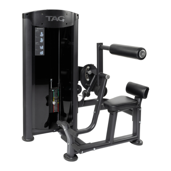
- Page 1 MODEL # S-Line 736 ABDOMINAL/LOWER BACK COMBO www.tagfitness.net 630-375-1500...
- Page 2 ABSTRACT PREVENTIVE MAINTENANCE................3 SPECIFICATIONS OF THE PRODUCT..............3 SAFETY INFORMATIONS..................4 ASSEMBLY........................5 Pictures and photos in this manual are merely illustrative. The company reserves the right to change specifications and design without notice. This manual may illustrate optional items which are not part of the equipment purchased.
- Page 3 PREVENTIVE MAINTENANCE SPECIFICATIONS OF THE PRODUCT Follow these guidelines to maintain perfect operation of the equipment. Note: For your convenience and quick access, the same information is applied in the product, sticker fixed on tower.
-
Page 4: Safety Informations
SAFETY INFORMATIONS Before using the equipment, carefully read all the safety labels and warnings related to the equipment as well as all the instructions contained in this Guide or the Equipment Installation Guide and retain them in a safe place for future reference. It is the owner's responsibility to ensure that all users of the equipment are adequately informed about the safety precautions and use. - Page 5 ASSEMBLY STEP 1 Assemble Tower Frame(1) to Main Frame(2) using Connecting Tube(3), Connecting Frame(5) and Connecting Frame(8), Fixing Plate(21), and Fixing Plate(22). To fix it use 14 Flat Washers(73), 2 Spring Washers(71), 6 Lock Nuts Hex M10(74), 2 Pan Head Allen Bolt M10x25(64), 2 Pan Head Allen Bolt M10x65 (65),6 Pan Head Allen Bolt M10x125(68) and 2 Pan Head Allen Bolt M10x100 (67).
- Page 6 STEP 2 Assemble Support Frame (6) to Tower Frame (1) using 2 Hex Head Bolt M10x25 (64), 3 Flat Washer (71), 3 Spring Washer (73). Do not tighten the bolts and nuts in this step. Nº English description SUPPORT FRAME TOWER GRAME HEX HEAD BOLT M10*25 FLAT WASHER...
- Page 7 STEP 3 Assemble Support Frame (6), Cam Support (7), Special Washer (23), Rotating Frame (9), Special Washer (23), Rotating Arm (4) to Connecting Frame (5), using Central Axle (14). In the 2 sides of Central Axle, fix 2 End Cap (28) with 2 Flat Head Allen Bolt M8x15 (62). Using right tools tighten bolts and nuts from the steps 1, 2 and 3 properly.
- Page 8 STEP 4 Fix the Pedal Bar (18) to Main Frame (2), using 2 Hex Head Bolt M8x15 (63), 2 Flat Washers M8 (72). Using right tools tighten bolts properly. Nº English description MAIN FRAME PEDAL BAR HEX HEAD BOLT M8*15 FLAT WASHER M8...
- Page 9 STEP 5 nstall 2 Base Cover(36) to Tower Frame(1) using 4 Pan Head Phillips Bolt M6x15(70). Nº English description TOWER FRAME BASE COVER PAN HEAD PHILLIPS BOLT M6X15...
- Page 10 STEP 6 Remove Cable (51) from Selector Shaft (30). Remove 2 Pan Head Allen Bolt M10x25 (59), 2 Spring Washer (71) and 2 Flat Washer (73) from Guide-rod (15). Incline Guide-rod (15) as shown in the drawing and then remove the combination of Top Weight Stack (29) and Selector Shaft (30). Make sure the shock absorber rubber and the weight lift are in the right position as shown in the drawing.
- Page 11 STEP 7 Insert Cable (51) onto Cam (7) and fix using 5 Allen Head Set Screw M8x8 (69). Using the right tools tighten bolts properly. Nº English description CABLE ALLEN HEAD SET SCREW M8X8...
-
Page 12: Completed Assembly
STEP 8 Fix 4 Side Face (33) in the Tower Frame (1) using 16 Pan Head Phillips Bolt M6x15 (70), 2 in the front and 2 in the back. Using the right tools tighten bolts properly. Insert 2 Front Cover (38) and 1 Back Cover (37) into Tower Frame (1). Then fix Bolt (19) on the Tower Frame (1) using 2 Pan Head Phillips Bolt M6x20 (75), Washer (76), Washer (78), and Big Washer (77), and using the right tools tighten bolts properly.
Need help?
Do you have a question about the S-Line 736 and is the answer not in the manual?
Questions and answers